Direct access of the buffer memory
The buffer memory of a special function module can also accessed directly, e. g. with a MOV
instruction.
The special function module addressed in this way can be mounted on a base unit or an exten
-
sion base unit but not in remote I/O stations.
Format of the device address:
For example the device address U3\G11designates the buffer memory address 11 in the spe
-
cial function module with the head address 3 (X/Y30 to X/Y3F).
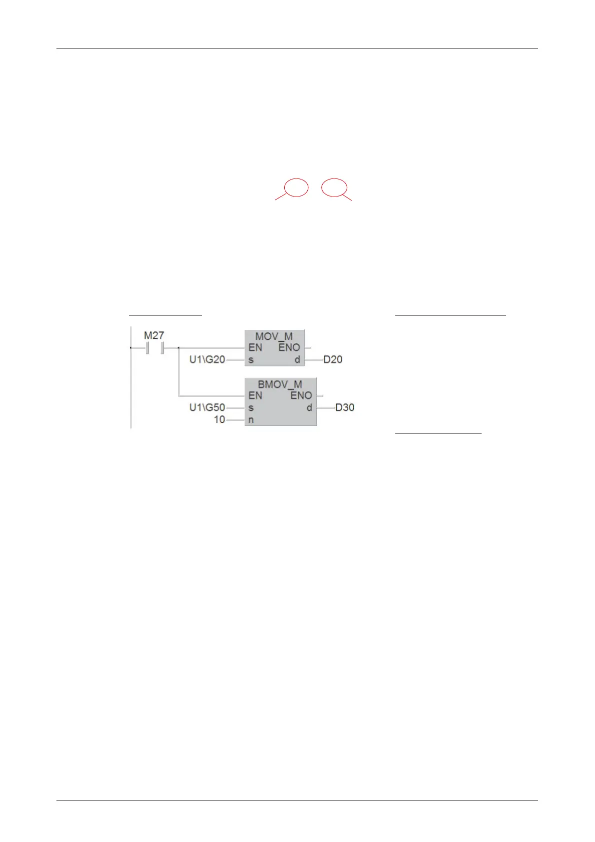
When relay M27 is set in the following example, the contents of the buffer memory address 20
of the special function module with the head address 1 is copied to data register D20. After
-
wards the contents of the buffer memory addresses 50 to 59 is copied into the data registers
D30toD39.
Automatic data transfer between PLC CPU and special function modules
Several add-in tools for the GX IEC Developer to set the initial data and condition data for spe
-
cial function modules are available. These tools simplify the configuration of special function
modules and facilitate the automatic data transfer between the PLC CPU and special function
modules. These optional software are commonly called GX Configurator. An extension to this
name denotes the affinity to certain special function modules.
In the software
GX Configurator-AD
for example all settings for analog input modules can be
made.To do this it is not necessary for the user to know the structure of the buffer memory. The
special function module parameters are downloaded in the PLC once together with the
sequence program.There is no need to transfer these settings in the sequence program.Thus
the size of the program is reduced and error sources are eliminated.
In GX Configurator-AD can also be specified where in the PLC CPU for instance measured val
-
ues should be stored. Afterwards this data transfer is processed automatically. FROM-/TO
instructions or the above described direct access to the buffer memory are not required.
MELSEC System Q Beginners Manual 6 – 21
More Advanced Programming Instructions for Moving Data
Uxxx\Gxxx
Buffer memory address
Head address of the special function module
Ladder Diagram
MELSEC Instruction List
LD M27
MOV U1\G20
D20
MOV U1\G50
D30
K10
IEC
Instruction List
LD M27
MOV_M U1\G20, D20
BMOV_M U1\G50, 10, D30

 Loading...


