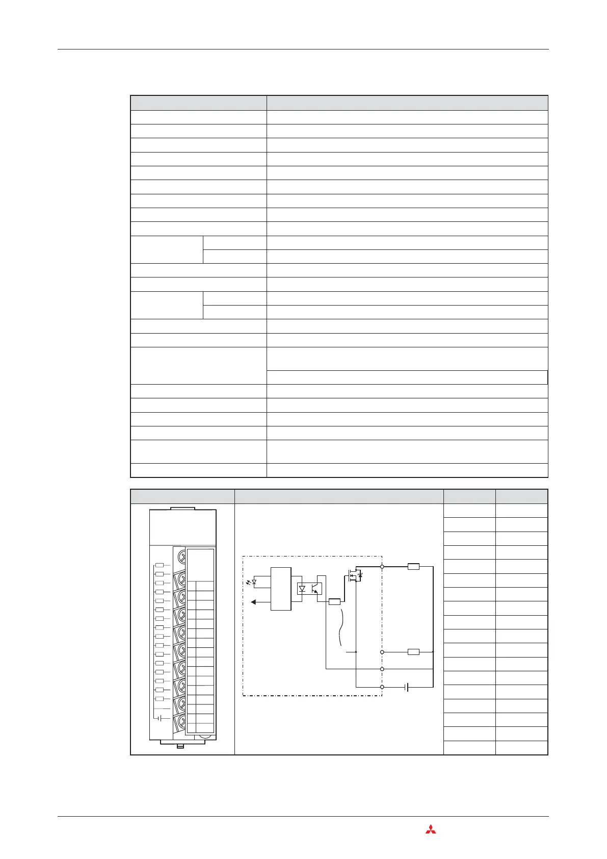
Example for a sink transistor output module
3–30 MITSUBISHI ELECTRIC
Das MELSEC System Q Digital Input and Output Modules
Item Specifications
Type of module QY40P
Number of output points 16
Isolation method Opto-coupler
Rated switching voltage 12 to 24 V DC (+20/-15%)
Switching voltage range 10.2 to 28.8 V DC
Maximum load current 0.1 A per output, 1.6 A per group
Maximum inrush current 0.7 A for 10 ms
Leakage current at OFF 0.1 mA or less
Maximum voltage drop at ON 0.1 V DC @ 0.1 A (TYP), maximum 0.2 V @0.1 A
Response time
OFF 씮 ON 1 ms or less
ON 씮 OFF 1 ms or less (rated load, resistive load)
Surge suppressor Zener diode
Fuse —
External power
supply
Voltage 12 to 24 V DC (+20/-15%, ripple ratio within 5%)
Current 10 mA (at 24 V DC and when all outputs are ON)
Dielectric withstand voltage 560 V AC rms/3 cycles (altitude: 2000 m)
Insulation resistance 10 M⏲ or more (by insulation resistance tester)
Noise immunity
By noise simulator of 500 V p-p noise voltage, 1애s noise width and 25 to
60 Hz noise frequency
First transient noise IEC61000-4-4: 1kV
Groups of outputs 1 group with 16 outputs (Common terminal: terminal 18)
Operation indicator 1 LED for each output
External connections 18-point terminal block (M3 x 6 screws)
Applicable wire size 0.3 to 0.75 mm
2
, core: 2.8 mm OD max.
Internal current consumption
(5 V DC)
65 mA (When all outputs are switched ON.)
Weigth 0.16 kg
Appearance Circuit Diagram Terminal Signal
1 Y00
2 Y01
3 Y02
4 Y03
5 Y04
6 Y05
7 Y06
8 Y07
9 Y08
10 Y09
11 Y0A
12 Y0B
13 Y0C
14 Y0D
15 Y0E
16 Y0F
17 12/24 V DC
18 COM
1
0
3
5
7
9
B
D
F
+-
2
4
6
8
A
C
E
12VDC
24VDC
0.1A
F
E
D
C
B
A
9
8
7
6
5
4
3
2
1
0
L
L
L
L
L
L
L
L
L
L
L
L
L
L
L
L
QY40P
1234567
89ABCDEF
COM
1
16
18
LED
17
12/24 V DC
Internal
Circuit
Output module

 Loading...


