EasyManua.ls Logo

Mitsubishi MELSEC System Q User Manual

Mitsubishi MELSEC System Q
170 pages
To Next Page IconTo Next Page
To Previous Page IconTo Previous Page
Page #76 background imageLoading...
Page #76 background image
Class
The class keyword assigns the variable a property that defines how it is to be used in the pro
-
ject. Some examples:
VAR: Local variable for use within the POU
VAR_EXTERNAL: An external global variable is declared in the Global Variable List and
can be read and written by all POUs.
VAR_CONSTANT: Local variable with constant value for use within the POU.
Identifier
Each variable is given a symbolic address. This individual name (identifier) can be chosen
freely but must always begin with a letter or a single underline character. Spaces and mathe
-
matical operator characters (e.g. +, - ,*) are not permitted.
Examples for identifiers:
S02.3
Drive_2_ready
_Open_Valve
Motor_M1_ON
The use of symbolic declarations complies with IEC 61131.3.
Absolute addresses
When global variables are declared they should also be assigned absolute addresses. If you
do not assign the absolute addresses manually, they are assigned automatically. An absolute
address specifies the memory location of the variable in the CPU or an input or output.
Absolute addresses can be assigned using either the IEC syntax (IEC-Adr.) or the MELSEC
syntax (MIT-Addr.). Some examples for absolute addresses:
Input X0F = X0F (MELSEC syntax) = %IX15 (IEC syntax)
Output Y03 = Y03 (MELSEC syntax) = %QX3 (IEC syntax)
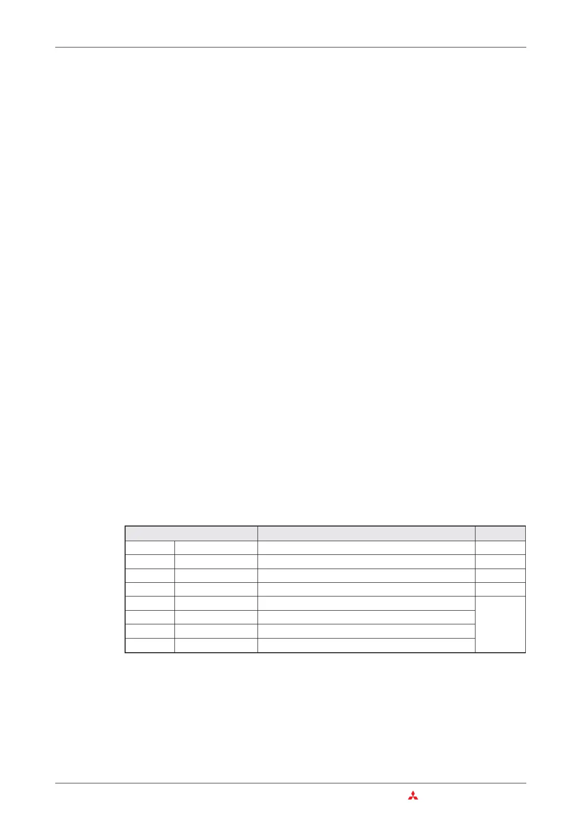
Elementary Data Types
The data type defines the characteristics of a variable like value range or number of bits.
4–12 MITSUBISHI ELECTRIC
The IEC 61131-3 Standard An Introduction to Programming
Data type Value range Size
BOOL Boolean 0 (FALSE), 1 (TRUE) 1 Bit
INT Integer -32768 to +32767 16 Bits
DINT Double Integer -2,147,483,648 to 2,147,483,647 32 Bits
WORD Bit string 16 0 to 65535 16 Bits
DWORD Bit string 32 0 to 4.294.967.295
32 Bits
REAL Floating point value 3.4E +/-38 (7 digits)
TIME Time value -T#24d0h31m23s64800ms to T#24d20h31m23s64700ms
STRING Character string Character strings are limited to16 characters

Table of Contents

Other manuals for Mitsubishi MELSEC System Q

Question and Answer IconNeed help?

Do you have a question about the Mitsubishi MELSEC System Q and is the answer not in the manual?

Mitsubishi MELSEC System Q Specifications

General IconGeneral
CategoryProgrammable Logic Controller (PLC)
TypeModular
SeriesMELSEC
I/O CapacityUp to 4096 points
Programming LanguagesLadder Logic, Structured Text, Function Block Diagram, Instruction List, Sequential Function Chart
Communication ProtocolsEthernet, CC-Link
RedundancyAvailable in certain models
Power Supply24 V DC, 100-240 V AC (depending on the power supply module)
Operating Temperature0°C to 55°C
Storage Temperature-25°C to 75°C
Humidity5% to 95% (non-condensing)
Shock Resistance147 m/s2 acceleration, 3 times in each of the X, Y, and Z directions
CPU TypeVarious CPUs available (e.g., Q00, Q01, Q02, Q06, Q12, Q13, Q26, Q100, Q172, Q173)

Summary

2 Programmable Logic Controllers

3 The MELSEC System Q

3.1 System Configuration

Details the modular structure and components of the MELSEC System Q.

3.2 Base Units

Describes available base units for mounting MELSEC System Q modules.

3.3 Power Supply Modules

Explains the function and types of power supply modules for MELSEC System Q.

3.4 The CPU Modules

Introduces different types of CPU modules available for the MELSEC System Q.

3.5 Digital Input and Output Modules

Describes the types and functions of digital input and output modules.

3.5.1 Digital Input Modules

Explains the specifications and considerations for digital input modules.

3.5.2 Digital Output Modules

Details the types, advantages, and specifications of digital output modules.

3.6 Special Function Modules

Introduces various special function modules for MELSEC System Q automation.

3.6.1 Analog Modules

Explains analog input and output modules and selection criteria.

3.7 Networks and Network Modules

Covers networking concepts and modules for MELSEC System Q communication.

3.7.4 Network Modules

Explains ETHERNET and MELSECNET modules for system communication.

4 An Introduction to Programming

4.7 The Basic Instruction Set

Provides a reference to basic instructions used in MELSEC PLC programming.

4.8 Safety First!

Emphasizes crucial safety precautions when working with PLCs and systems.

4.9 Programming PLC Applications

Demonstrates PLC application development with a practical example.

4.9.1 A rolling shutter gate

Presents a detailed example of programming a rolling shutter gate control system.

4.9.2 Programming

Guides through the process of creating a new PLC project and assigning variables.

5 Devices in Detail

5.1 Inputs and Outputs

Explains how PLC inputs and outputs connect to the controlled process.

5.2 Relays

Details the function and types of relays (normal and latched) in PLC programs.

5.3 Timers

Describes programmable internal timers, their function, and types (low/high speed, retentive).

5.4 Counters

Explains internal counters for programming counting operations and their features.

5.5 Registers

Covers registers for storing measurements and calculation results (16-bit and 32-bit).

5.5.1 Data registers

Details data registers used for memory storage in PLC programs.

6 More Advanced Programming

6.1 Applied Instructions Reference

Provides a reference for advanced PLC instructions beyond basic logic.

6.2 Instructions for Moving Data

Explains instructions for moving data between registers and devices.

6.2.5 Exchanging data with special function modules

Details using FROM/TO instructions for data exchange with special function modules.

6.3 Compare Instructions

Explains instructions for comparing values (numerical, string) in PLC programs.

6.4 Math Instructions

Covers basic arithmetic operations like addition, subtraction, multiplication, and division.

Related product manuals