5
No. 99MBC139A
1 Overview
1.4 Part Names
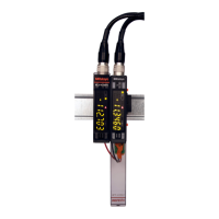
1.4.1 Main Unit
① Linear Gage input con-
nector (INPUT A/B)
Display (See 1.4.2.)
⑤ Connector for linking counter (female)
Serial label
Pin assignment label
⑥ DIN rail attachment point
Rear side
③ I/O connector
Front side (with cover)
Front side (without cover)
④ Grounding terminal
② Connector for linking counter (male)
No. Name Description
①
Linear Gage
input connector
(INPUT A/B)
Linear Gages can be connected to each of inputs A and B.
The Linear Gage connected to INPUT A is referred to as the
A-axis, and that connected to INPUT B as the B-axis.
②
Connector for linking
counter (male)
Allows connection to another EJ Counter or optional interface
unit.
③
I/O connector For connection to the power supply or external equipment using
the provided connector plug.
④
Grounding terminal For connection to ground using the provided ground lead and
ground plate.
⑤
Connector for linking
counter (female)
Allows connection to another EJ Counter or terminal resistance
unit.
Tips
A terminal resistance unit is provided with the optional interface unit.
⑥
DIN rail attachment point Used for attaching the counter to a DIN rail.
 Loading...