43
No. 99MBC139A
4 Data Output
4.1.3 Pin Assignments
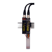
Pin arrangement (connector built into EJ Counter)
1 3 5 7 9
2 4 6 8 10
Tips
For details on the input/output circuit, see "4.1.4 Input/Output Circuits" on page 45.
■Input
Photo coupler input (negative logic)
■Output
Photo coupler collector output (negative logic)
Tips
Output is in the error state while setting the preset and tolerance values and while setting parameters.
Pin
number
Signal name Signal level
7
ALLGO (when Parameter Number 10 is set to 1) H
ERR (when Parameter Number 10 is set to 0) L
8 LT1 L
9 LT2 H
10 LT3 L
■Signal
Pin
number
Signal name IN/OUT Functions
1 10-27V DC IN Power source (supplied to EJ Counter from an external source)
Input power: 10 V–27 V, 3 A
2 GND IN
3 1/2 SEL IN
Speciesthechannelforinput/outputsignals.
H: Ch. 1
L: Ch. 2
Tips
• When Parameter Number 11 is set to 1, the display channel can be
changed by switching between H and L.
• When disconnected (open), the signal level goes H.
 Loading...
