This document and the information contained herein, is the exclusive property of MODE. And represents a nonpublic,
confidential and proprietary trade secret that may not be reproduced, disclosed to third parties, or otherwise employed in
any manner. whatsoever without the express written consent of MODE. Copyright © (2016) MODE. Allrights reserved.
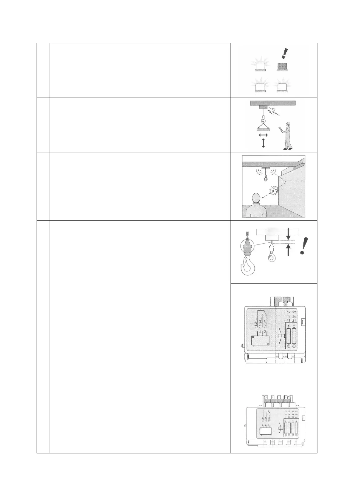
Warning devices
Check that all warning devices (for example, pilot lamps, LEDs,
displays, horns, gongs, bells, sirens, beacons, strobe lights) are
working correctly before using the hoist.
Control devices with power
Starting at low speed, check that movements correspond to the
controller labels. Check that the brakes operate in all directions and
that the speed increases as it should do in relation to the control.
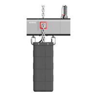
Upper and lower limit switches (Configuration B)
Check the condition of the rubber pad on top of the hook and also
on the other end of the chain, at the chain bag. The plastic rings
activate the upper and lower limit switches on the hoist. If a plastic
ring is broken then it is a sign that a limit switch is not functioning
correctly.
Check for correct operation of the limit switches by raising and
lowering the hook at low speed until the limit switches are
activated and prevent further upward or downward movement.
Hoisting limit switch
Adjusting the limit switch
First check the operation of the limit switch, see instructions under
Test Run Without Load’.
After checking the operation of the limit switch:
In case the hoist is equipped with geared limit switch, the cutting
points of this device need to be adjusted before hoist operation
starts. Geared limit switch is accessed by opening the end cover of
hoist from the brake side. Adjustment is done by turning the
setscrews (1)... (4) (depending on the number of switching
elements):
Turning to the left: switching point is moved "downwards".
Turning to the right: switching point is moved "upwards".
2-step geared limit switch
Setscrew 1 is the down limit and setscrew 2 the upper limit.
4-step geared limit switch
Setscrews 1 and 2 are the down limit and setscrews 3 and 4 the
upper limit.
HOL