moog
MSD Servo Drive DC-AC Operation Manual
56
Id.-No.: CA97554-001 Date: 06/2012
to glossaryto table of contents
UVW
+ −
max. 8 A
+ − − +− +− +− +
UVW
24 V DC
L1 L2
L3 − +− +
X12
X12X12
X11 X9/10
X9/10X9/10
X11X11
L1 L2 L3 PE
PE
Motor
3~
Motor
3~
UVW
Motor
3~
1
2
7
4
3
9
13
15
10 11 11
14
ϑ
8
12
L1.1
L2.1
L3.1
L1
L2
L3
6
L3
L2
L1
L3.1
L2.1
L1.1
L3
L2
L1
L3.1
L2.1
L1.1
5
RB ZK
+ −
− +
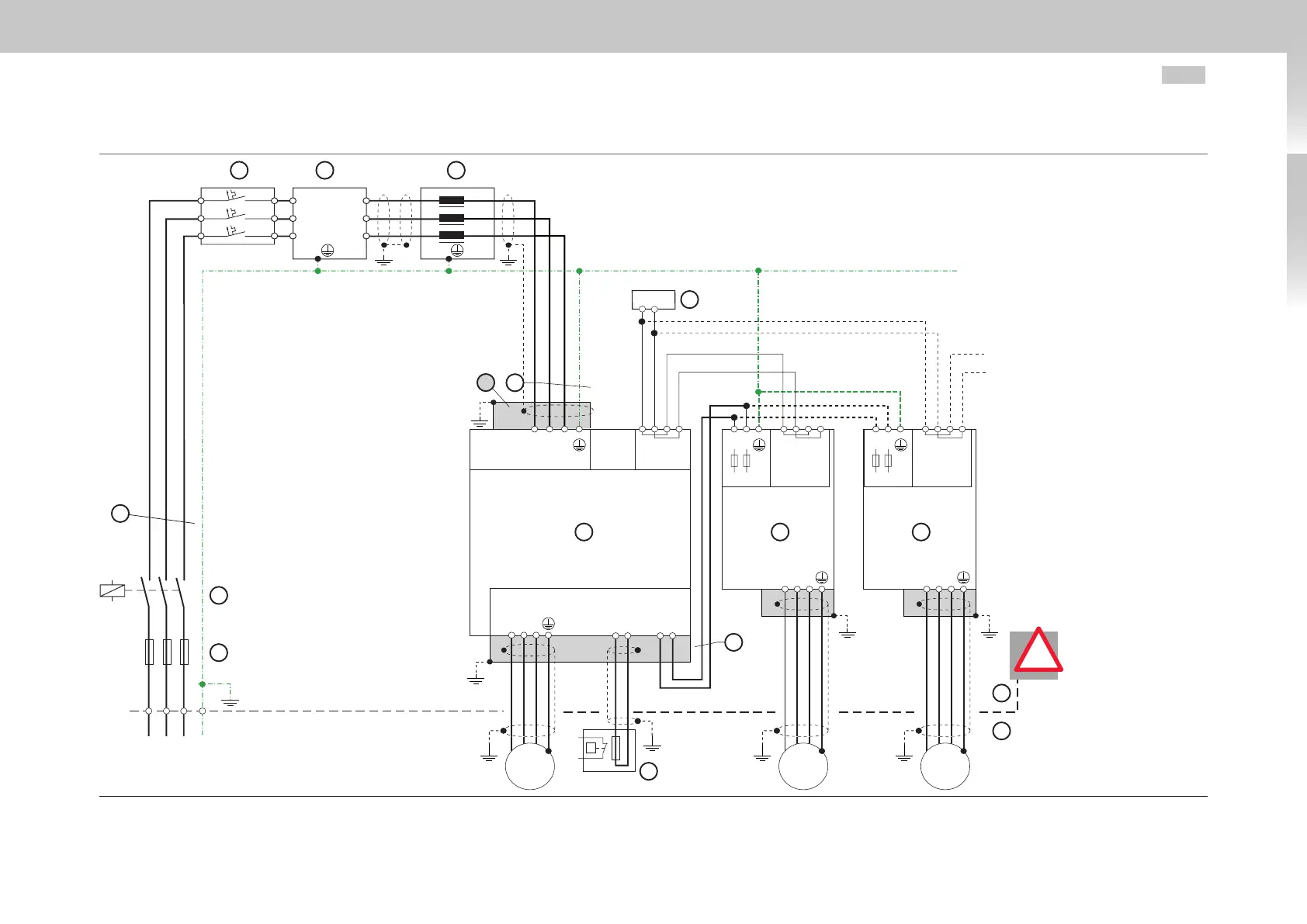
Fig. 7.2 Overview - Connection diagram for operation with supply by AC-AC servo drive (Size 5 to Size 6A)
Key
1. Mains fuses
1)
2. Mains supply/Emergency
stop
3. Short-circuit-proof cables
4. for Size 5: Motor protection
switch
1)
5. Mains choke
6. Mains filter
7. AC power connection
8. Shield (grey)
9. External 24VDC control
supply (fuse-protected)
10. MSD Servo Drive AC-AC
(Size 5 to Size 6A)
11. MSD Servo Drive DC-AC
12. DC link
13. Switch cabinet
14. Field
15. Braking resistor
1)
1)
ATTENTION:
Observe the require-
ments for device pro-
tection on page53!
!

 Loading...


