MSD Single-Axis System Operation Manual AC-AC Servo Drive
ID no.: CA65642-001 06/2018
moog
31
Electrical installation
Motor brake
GND
GND
X20/2
X20/3
X20/1
X20/4
#)
#)
#) only for hardware
Versionen 0 and 1
Up to hardware version 2
replaced by 0 Ω each.
#)
PE GNDµP
DGND
complexe,
impedance in
part non lineare
RC
element
Polyswitch
GNDµP
GNDµP
GNDµP
X4/15
ISD00
ISD01
I
LIM
X4/21
ISD06
X4/10
ENPO
I
LIM
X4/22
ISDSH
I
LIM
X4/7
OSD00
X4/3
ISA00+
PTC of the motor
X4/4
ISA00-
ISD02
ISD03
ISD04
ISD05
A/D
A/D
ISA01+
X4/5
X4/6
ISA01-
X4/14
GNDµP
GNDµP
GNDµP
GNDµP
GNDµP
DGND
DGND
DGND
DGND
DGND
DGND
DGND
DGND
X4/2
ϑ
F1
ϑ
F2
X4/13
DGND
X4/1
ϑ
F3
ϑ
F3
GNDµP
GNDµP
GNDµP
ϑ
F4
V
µP
V
µP
V
µP
V
µP
µP
X4/8
OSD01
X4/9
OSD02
54
321
98
76
54321
10 9876
15 14
13 12
11
X40/
ϑ +
X40/ϑ −
RSH
X4/12
X4/11
OSD04
OSD03
+24 V
X4/23
X4/24
USB1.1
X2
Ethernet
X3
Resolver
X6
Encoder/SSI
X7
GNDµP
V
µP
PE
U
V
U
V
X9/+
X9/-
X10/+
X10/-
U
H
Control
supply
24 V DC
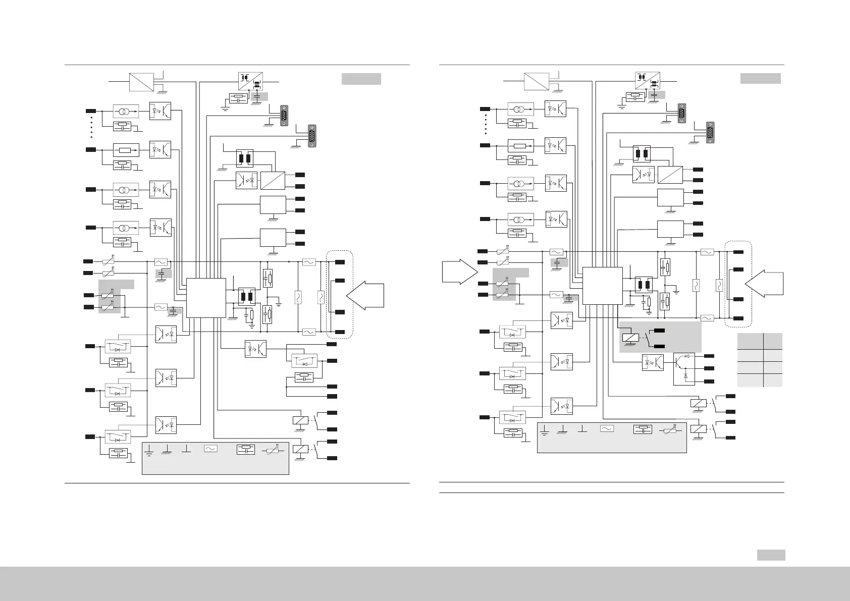
Figure 4.12 Electrical isolation concept for Size 1 to Size 4
24V DC
OSD03
Motor brake
GND
X20/1
X20/2
X20/3
Size 7
only Size 7
Size 5
and
Size 6A
X44/5
X44/6
X44/7
#)
#)
#) only for hardware
versions 0 and 1
Up to hardware version 2
replaced by 0 Ω each.
#)
PE GNDµP
DGND
complexe,
impedance in
part non lineare
RC
element
Polyswitch
GNDµP
GNDµP
GNDµP
X4/15
ISD00
ISD01
I
LIM
X4/21
ISD06
X4/10
ENPO
I
LIM
X4/22
ISDSH
I
LIM
X4/7
OSD00
X4/3
ISA00+
PTC of the motor
X4/4
ISA00-
ISD02
ISD03
ISD04
ISD05
A/D
A/D
ISA01+
X4/5
X4/6
ISA01-
X4/14
GNDµP
GNDµP
GNDµP
GNDµP
GNDµP
DGND
DGND
DGND
DGND
DGND
DGND
DGND
DGND
X4/2
ϑ
F1
ϑ
F2
X4/13
DGND
X4/1
ϑ
F3
ϑ
F3
GNDµP
GNDµP
GNDµP
ϑ
F4
V
µP
V
µP
V
µP
V
µP
µP
X4/8
OSD01
X4/9
OSD02
54321
9876
54321
10 9876
15 14
13 12 11
X5/ϑ +
X5/ϑ −
RSH
X4/12
X4/11
OSD04
X4/23
X4/24
USB1.1
X2
Ethernet
X3
Resolver
X6
Encoder/SSI
X7
GNDµP
V
µP
PE
U
V
U
V
X9/+
X9/-
X10/+
X10/-
U
H
Control
supply
24 V DC
GNDµP
X44/3
X44/4
internal
potential
free relay
Control
supply
24 V DC
*)
*)
*)
*) For Size 5, also connect the 24 V DC control supply to control terminals. Internal connection is not available.
Figure 4.13 Electrical isolation concept for Size 5 to Size 7