M Series AC Servo
User Manual
93
Rev. 1.1
9/13/2021
400-820-9661
7.3.2 Parameter Settings For Analog Velocity Control Mode
M2 series AC servo drive has 2 12bits analog AD converters. When single ended input signal is used,
analog input 1 (ANA1) is used for velocity command, analog input 2 (ANA2) is used for rotating toque
command. Dierential input via ANA1/ANA2 is also available. In addition, low pass lter, oset and
deadband can also be set to the drive.
Parameter Name Data Range Default Unit Description
P-12 (CM) Main control mode 1~8,10~18,21,22 7 Drive
’
s main control mode selection
P-13 (CN) Secondary control mode 1~8,10~18,21,22 21 Drive
’
s secondary control mode selection
P-50 (AG) Analog Velocity Gain -100~100 20 Rps
Motor rotating velocity when analog
voltage is 10VDC
P-51 (AN) Analog Torque Gain -20~20 1 A
Motor rotating torque when analog voltage
is 10VDC
P-52 (AV1) Analog voltage oset 1 -10~10 0 V Set analog voltage input 1 oset value
P-53 (AV2) Analog voltage oset 2 -10~10 0 V Set analog voltage input 2 oset value
P-54 (AV3)
Analog voltage oset
(dierential)
-10~10 0 V
Set dierential analog voltage input oset
value
P-55 (AS) Analog input type 0~1 0 Analog input type
P-56 (AD1) Analog deadband 1 0~255 0 mV Set analog input 1 deadband oset value
P-57 (AD2) Analog deadband 2 0~255 0 mV Set analog input 2 deadband oset value
P-58 (AD3)
Analog deadband
(dierential)
0~255 0 mV
Set analog dierential input deadband
oset value
P-59 (AF)
Analog input low pass
lter
1~15990 500 Analog input noise lter
P-60 (AT) Analog trigger point -10~10 0.000 V
P-61 (FA1)
Dene Analog input 1
function
1~3 3 Dene Analog input 1 function
P-61 (FA2)
Dene Analog input 2
function
1~3 3 Dene Analog input 2 function
NOTE: This parameter unit in table above might be different from the LED display unit on the
drive. Please refer to parameter 8 for details.
7.3.3 Basic Settings For Analog Velocity Control Mode
7.3.3.1 Command Signal For Analog Velocity Mode
In Analog input velocity mode, both single ended and dierential signal are acceptable.
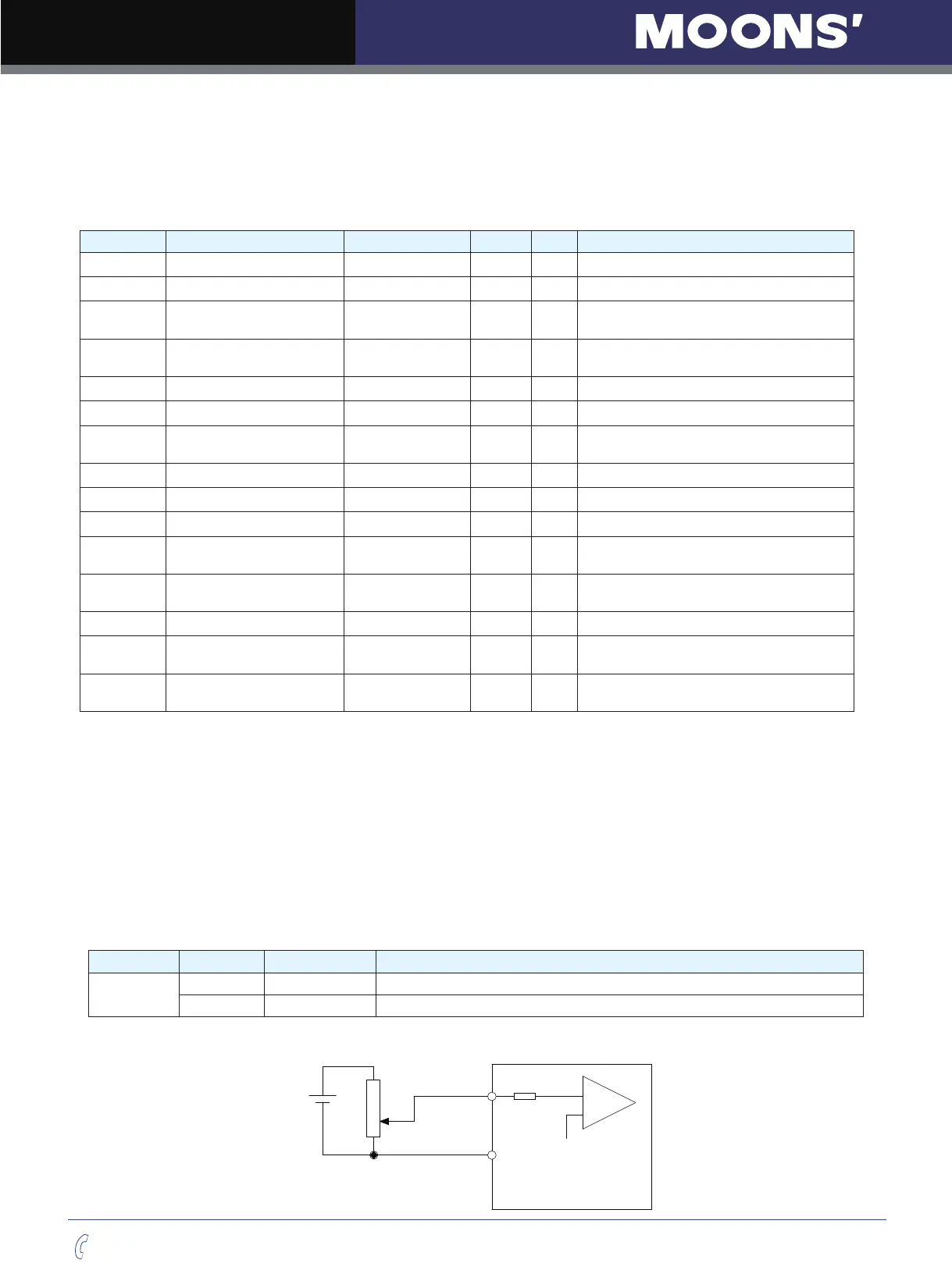
A. Single Ended Analog Input
PIN type Signal PIN number Function
Input
ANA1 16 Analog velocity input signal
DGND 15 Analog velocity input signal grounding (digital ground)
Single ended analog input
16(18)
ANA1(ANA2)
15(17)
DGND
+
-
±10VDC