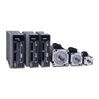
M Series AC Servo
User Manual
28
Rev. 1.1
9/13/2021
400-820-9661
4.1.2 Servo Drive Connectors and Terminals
Terminal Identication Description Details
P1
L1
、
L2
、
L3 Used to connect three-phase AC main circuit power
L1C
、
L2C Used to connect single-phase AC for control circuit power
P2
U
、
V
、
W
Used to connect servo motor
Terminal
Symbol
Wire color Description
U Red
Connecting to three-phase
motor main circuit cable
V Yellow
W Blue
B1+
、
B2
、
B3
Regenerative resister terninals
Internal
Resister
Ensure the circuit is closed between B2 and B3,
and the circuit is open between B1+ and B3.
External
Resister
Ensure the circuit is open between B2 and B3,
and connect the external regenerative resister
between B1+ and B2.
CN1 Communication Port User to connect personal computer
CN2 I/O Connector Used to connect external controllers.
CN3 Encoder Feedback Connector Used to connect encoder of servo motor.
CN4 Reserved
CN5 Reserved
CN6
RS-485/CANopen
*RS-232 Communication Port
RJ45 connector, Daisy Chain, Used for RS-485/CANopen
*RS-232 Communication Port (-Q Type Only)
CN7
RS-485/CANopen
Communication Port
RJ45 connector, Daisy Chain, Used for RS-485/CANopen
Communication
4.1.3 Connections and Wiring Notes
• Please ensure grounding wires are securely connected, wires with more than 2.0mm
2
on sectional area
is recommended.
• Grounding method must be single point grounding.
• Ensure L1/L2/L3 and L1C/L2C are correctly wired, and voltage supplies are within the specication
range.
• Ensure U/V/W is following the order of RED/YELLOW/BULE. Wrong connections will cause motor stop
rotation, or wrong rotatory directions.
• Isolation transformer or EMI lter is recommended on drive
’
s power supply to ensure drive
’
s safety and
improve its anti-interference level.
• Please setup an emergence stop circuitry to switch o the power supply when fault occurs.
• Please DO NOT touch drive or motor
’
s connector terminals 5 minutes after drive and motor is powered
o. There are electrical charge components in the circuitry. Therefore, even power is o, there might still
be hazardous voltages within the circuitry, before its total discharge.
• Install the encoder cables in a separate conduit from the motor power cables to avoid signal noise.
Separate the conduits by 30cm (11.8inches) above.
• Use multi-stranded twisted-pair wires or multi-core shielded-pair wires for signal, encoder feedback
cables.
• The maximum length of signal input/output cable is 5 meters, and the maximum length of encoder (PG)
feedback cables is 15 meters.

 Loading...