I/O Modules
5-8
10) Label the TBs wires with any desired user notes. The wires are numbered 1-20 or 1-40
depending on the model. The wire numbers correspond to the module pins.
11) To extract the TB holder from the I/O module front panel, extend the ejector handles
outward away from the module and pull on the handles.
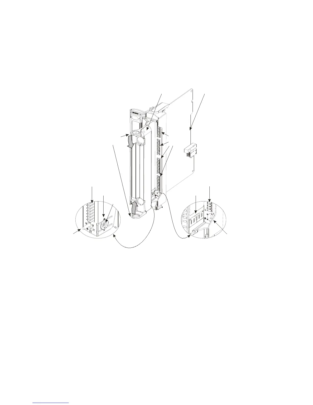
Figure 5-8 provides a general view of the TB holder and an I/O module.
TB Holder
Terminal
Blocks (TB)
Ejector
Handles
Code Key
O
F
O
F
U
F
1
6
24V
Positioner
Terminal Block (TB)
I/O Module
Code Key
Positioner
Terminal Block (TB)
TB Holder
Screw
I/O Module
Figure 5-8 Terminal Block (TB) Holder on I/O Module – General View with Coding
Wired Cable Braid
The optional three-meter cable braid is completely wired with a TB holder and either 20 wire
or 40-wire cable. Each wire in the cable is labeled with the corresponding pin number. This
information is useful when connecting the PGND to the grounding strip. See the Connecting
I/O Modules to Ground section of the Installation chapter.

 Loading...


