May 25, 2005 6881096C74-B
3-34 Theory of Operation: Transmitter
Dual Final Stage
C5530, C5531, C5532, C5533, C5536, C5537-41 and transmission lines form a low pass, splitter
match that transfers power to the LDMOS dual final-stage transistors Q5541 and Q5540. Q5540 and
Q5541 contain two transistors in a single package, each with it's own gate and drain lead. R5542-5,
R5548-51 provide stability for Q5540. R5552-5, R5557-60 provide stability for Q5541. R5546, C5602
and C5542 supply the VGBIAS1 gate bias to Q5540. R5581, C5550 and C5603 supply the VGBIAS2
gate bias to Q5541. L5543, L5544, R5574, C5567 and C5568 form the A+ drain bias circuit to Q5540
and Q5541. C5551-56, C5559-66, C5584, C5587, C5589 and transmission lines form a low -pass
combiner match that transfers approximately 100 W to the antenna switch. R5562 provides stability
for Q5540. R5573 provides stability for Q5541. Both Q5540 and Q5541 operate Class AB.
R5575 and U5561 comprise the final-stage, current-sense circuit that generates the VCURRENT
voltage proportional to the final stage current. R5578 sets the circuit gain. U5560 generates the
VTEMP voltage, which is proportional to the final-stage temperature.
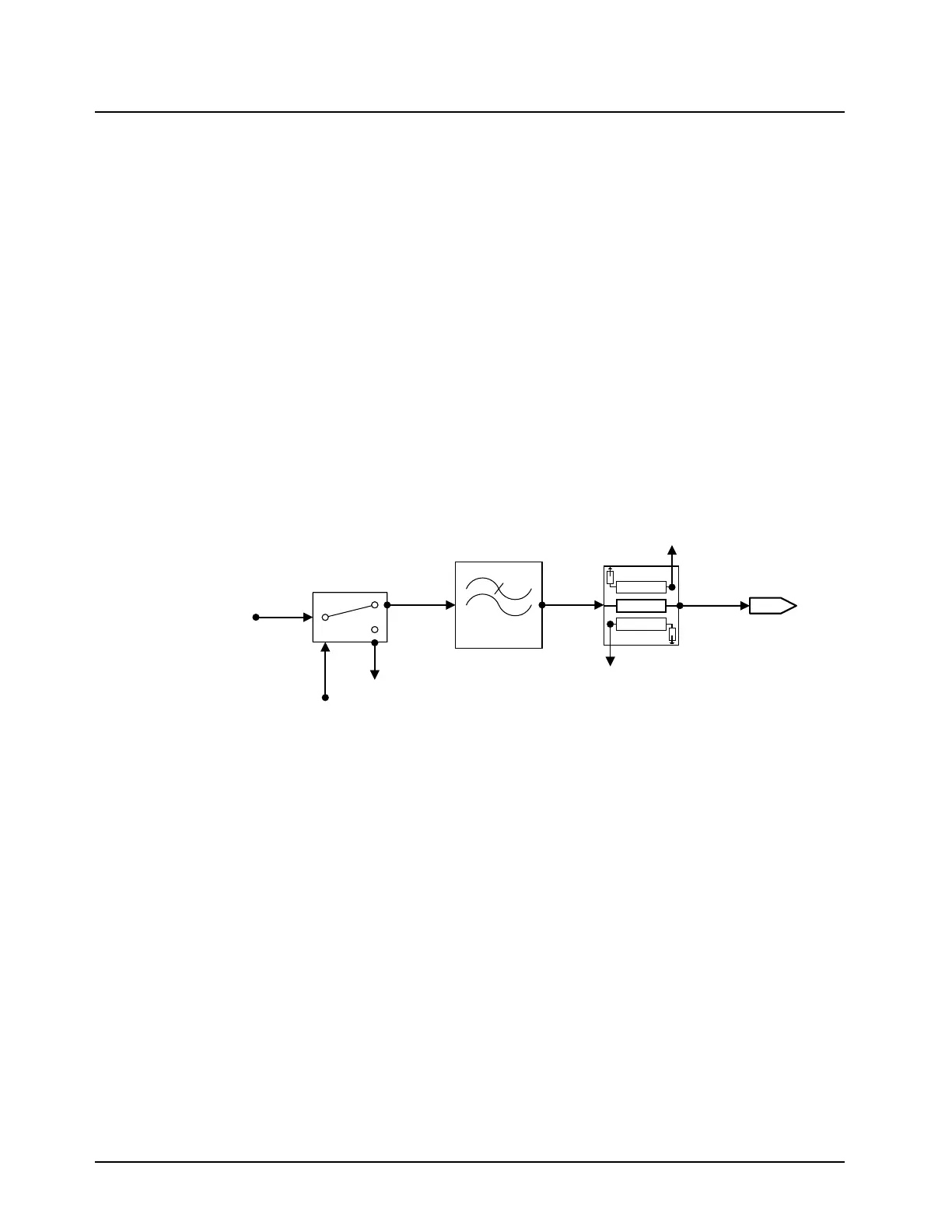
3.6.2.3 Output Network (ON) - (for 40W and 100W Transmitter)
The ON consists of the antenna switch, harmonic filter, and power detector (see Figure 3-27).
Figure 3-27. Output Network Components (UHF Range 1)
Antenna Switch
The antenna switch functions in two modes determined by the presence of K9.1V. The K9.1V switch
bias is applied via L5701and C5702. When K9.1V is present, the switch is in TX mode. D5701,
D5702 and D5703 are forward biased forming a low-loss path from the RFPA final stage to the
harmonic filter and a 20 dB isolation path between the RFPA final stage and the RX front-end.
Isolation is achieved via a quarter-wave transmission lines between D5701 - D5702 and between
D5702 - D5703. C5709-10 resonates out the D5702-3 on inductance improving the isolation. When
K9.1V is absent, the switch is in RX mode. D5701, D5702 and D5703 are reverse biased forming a
low-loss path from the harmonic filter to the RX front-end and a 20 dB isolation path from the
harmonic filter to the RFPA final stage. Isolation is achieved via the D5701 off resistance. L5702
resonates out the D5701 off capacitance improving the isolation.
Harmonic Filter
The harmonic filter is a 7-element, equal-L Zolotarev quasi-lowpass filter consisting of C5712 and
C5713, C5719 thru C5721 and L5706 thru L5708. L5712, C5711 and L5713, C5714 form two shunt
zeros for extra attenuation at the second harmonic. C5708 acts as a DC block between the filter and
the antenna switch. The filter provides approximately 60 dB of harmonic rejection. The harmonic
filter together with the antenna switch provides approximately 0.7 dB insertion loss between the
transmitter power amplifier and the antenna.
RFPA_OUT
ANTENNA
SWITCH
H-FILTER
POWER
DETECTOR
RF
CONNECTOR
From
RFPA
51W
K9.1V
VREVERSE
VFORWARD
J5701
44W
RX_IN

 Loading...


