6881096C74-B May 25, 2005
Theory of Operation: Receiver Front-End 3-19
3.4.4 700–800 MHz Band
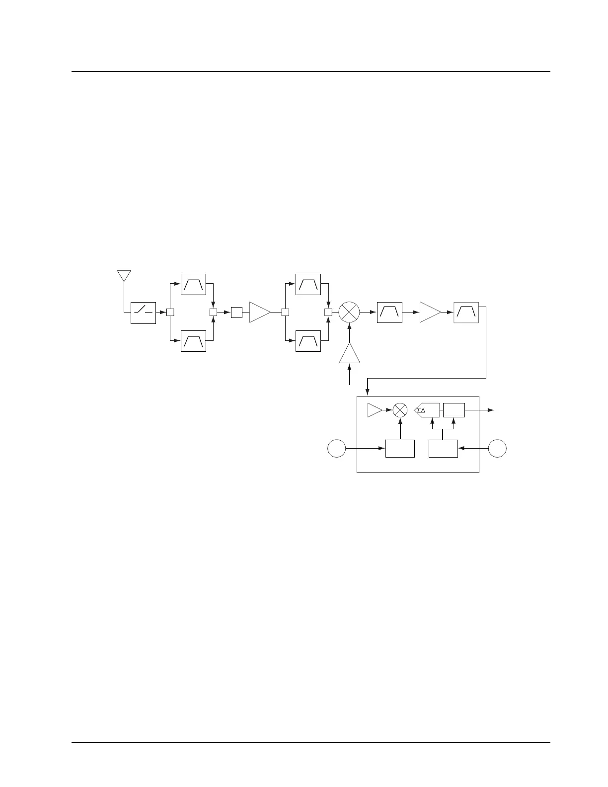
The receiver circuits primary duties are to detect, filter, amplify, and demodulate RF signals in the
presence of strong interfering noise and unintended signals. The receiver (see Figure 3-16) is
broken down into the following blocks:
• Front-end, which includes:
- Preselector filters
- Low-noise amplifier (LNA)
- First mixer
•IF
• Back-end
Figure 3-16. Receiver Front-End and Back-End (700–800 MHz)
3.4.4.1 Preselector Filters
The front-end operates in the 700 MHz and 800 MHz bands. The front-end's primary function is to
optimize image rejection and selectivity while providing the first conversion. The front- end uses fixed
ceramic-filter technology. There are two sets of filters: (B6250 and B6252) for the 800 MHz band and
(B6251 and B6253) for the 700 MHz band. These filters are switched between bands by a network of
diode switches (D6251 thru D6257) biased by RLC networks (C6254, C6260, R6254, and L6254)
that also act as RF chokes. The first filter is a dual-switched filter that reduces the image-frequency
response and limits some of the out-of-band interferers. The second filter following the monolithic
low-noise amplifier (LNA) provides additional image rejection.
3.4.4.2 Low-Noise Amplifier (LNA, U6250)
A diode (D6258) located after the first preselector and before the LNA protects the receiver from
strong RF signals by limiting the signal amplitude going into the amplifier. The LNA is a low-noise
monolithic IC providing ~ 16 dB of gain to the receiver. It is biased with 5 V at pins 1 and 6. The input
matching consists of an LC network (C6288, L6258) for optimal gain.
LNA
Ant. SW.
Harm. FLT
Mixer
Preselect 2
Preselect 1
RF Input
Crystal
15dBm
1st LO
Backend A/D Converter
SSI
Dec.
Filter
CLK
Synth.
LO
Synth.
2nd
LO
18MHz
CLK
IF Amp Crystal
73.35MHz
A
700MHz
800MHz
MAEPF-27905-O
ADC
ABACUS III IC

 Loading...


