6881096C74-B May 25, 2005
Product Overview: Control-Head Assembly 2-5
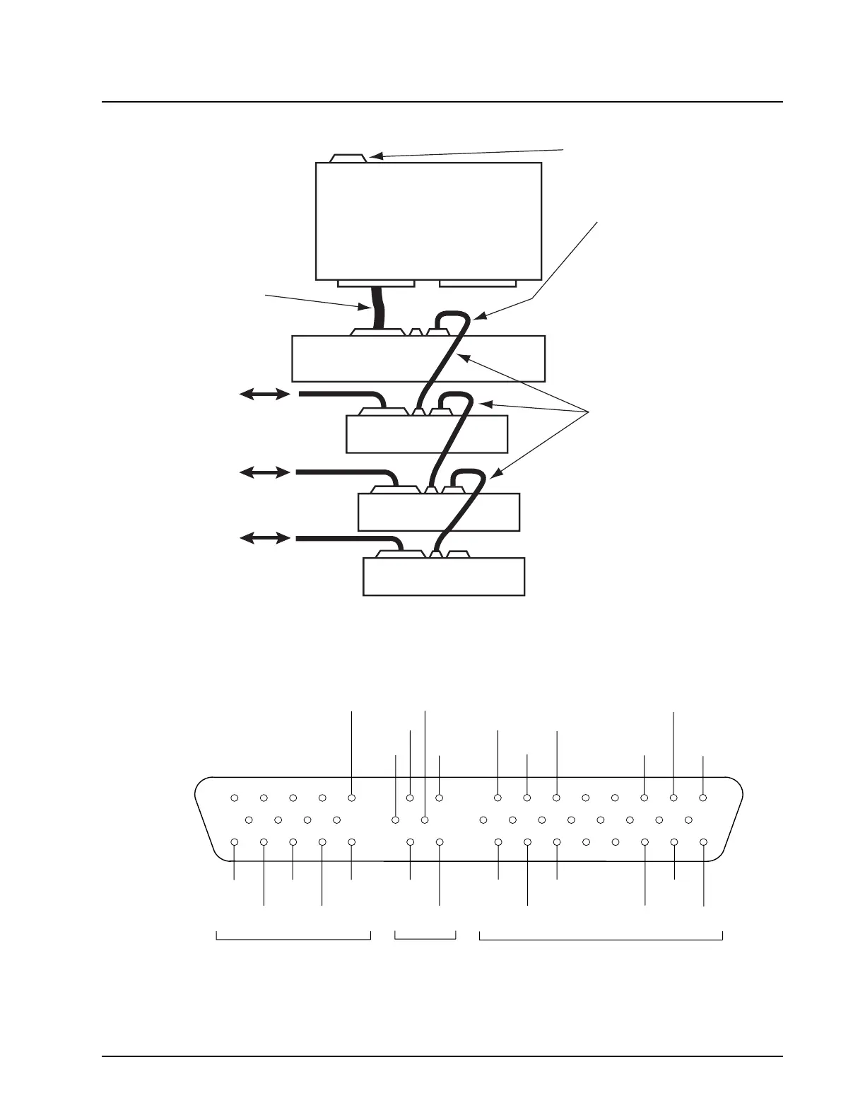
Figure 2-5. VIP Remote-Mount Plus DEK Configuration
Figure 2-6. VIP Remote-Mount Plus DEK Pin-Outs (Male)
Kit HKN4273 contains:
- One DEK-to-DEK interface cable (A)
- One 24-pin DEK VIP connector (B)
- One 14-pin non-DEK VIP connector
- Forty cimping pins
(A) DEK interface lines:
DATA IN
DATA OUT
STROBE
CLOCK
When a DEK is added, the
radio VIPs move from J2
and from the back of the
control head to the back of
the DEK.
Main Board
(Radio)
Control Head
(W4, W5, W7, W9)
DEK A
DEK B
DEK C
SB9600 bus
messaging
interface
3 VIP - INs
3 VIP - OUTs
3 VIP - INs
3 VIP - OUTs
3 VIP - INs
3 VIP - OUTs
MAEPF-27925-O
(B)
1 2 3 4 5 7 8 10 11 12 13 14 15 16 17
18 19 20 21 23 24 26 27 28 29 30 31 32 33
34 35 36 37 38 40 41 43 44 45 46 47 48 49 50
STROBE GND CLOCK DATA VIP OUT VIP OUT SWB+
SWB+ DATA SWB+ VIP OUT SWB+ SWB+
OUT
IN
1
3
OUT STROBE 2
GND GND GND
3
2
FROM
CONTROL HEAD
OR PREVIOUS DEK BOX
TO NEXT DEK BOX DEK VIP-INs AND VIP-OUTs
IN
GNDCLOCK
DATA VIP IN VIP IN
DATA
VIP IN
MAEPF-27917-O
1

 Loading...


