May 25, 2005 6881096C74-B
4-30 Troubleshooting Procedures: Standard Bias Tables
RS232__UARTA_RTS Flow control line—not
used always
TP0410, J2-10
Note: Use chassis as GND when measuring on an oscilloscope.
Approx. 0 V Emergency Idle = deactivated =
grounded
J2-15, J0402-28,
TP0403
1.88 V Emergency Activated = ungrounded J2-15, J0402-28,
TP0403
Approx. 0 V Emergency_sense Deactivated U508-4
2.85 V Emergency_sense Activated U508-4
(See “Chapter 6
Troubleshooting
Waveforms” on
page 6-1)
Boot_TX Same as UARTA_TX J0401-26, P502-10
Boot_RX Same as UARTA_RX J0401-25, P502-2
2.85 V Cable_Detect No prog. cable inserted U0402-4
0 V Cable_Detect Prog. cable inserted at
P502
U0402-4
3.5 V Boot_Data_enable No prog. cable inserted
0 V Boot_Data_enable Prog. cable inserted at
P502
U0402-2
0 V Opt_B+_bootsel_Vpp No prog. cable inserted J0401-22, TP0401
8 V Opt_B+_bootsel_Vpp Prog. cable inserted @
P502
J0401-22, TP0401
(See “6.2.5
32 kHz Clock
Waveform” on
page 6-4)
32 kHz U0102-4
(See “6.2.4
16.8 MHz Clock
Waveform” on
page 6-3)
16.8 Mhz C0911 near U0903
Note: Do not KEY UP unless the board is inside a chassis.
Table 4-18. Standard Operating Bias: Audio Lines
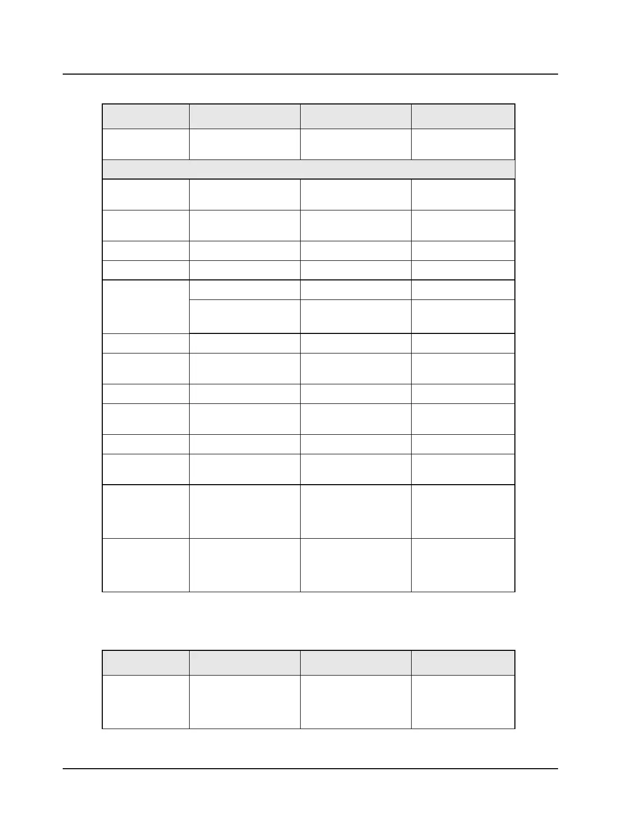
Nominal Value Signal Name Range/State Probe Locations
9.2 V Mic_Hi When microphone
connected (expects
80 mV input) (line has
microphone bias)
TP0402, J0401-4
Table 4-17. Standard Operating Bias: Clock and Control Lines (Continued)
Nominal Value Signal Name Range/State Probe Locations

 Loading...


