EasyManuals Logo

Motorola ASTRO Digital XTL 5000 Detailed Service Manual

Motorola ASTRO Digital XTL 5000
528 pages
To Next Page IconTo Next Page
To Previous Page IconTo Previous Page
Page #71 background imageLoading...
Page #71 background image
6881096C74-B May 25, 2005
Theory of Operation: Main Board Major Sections 3-5
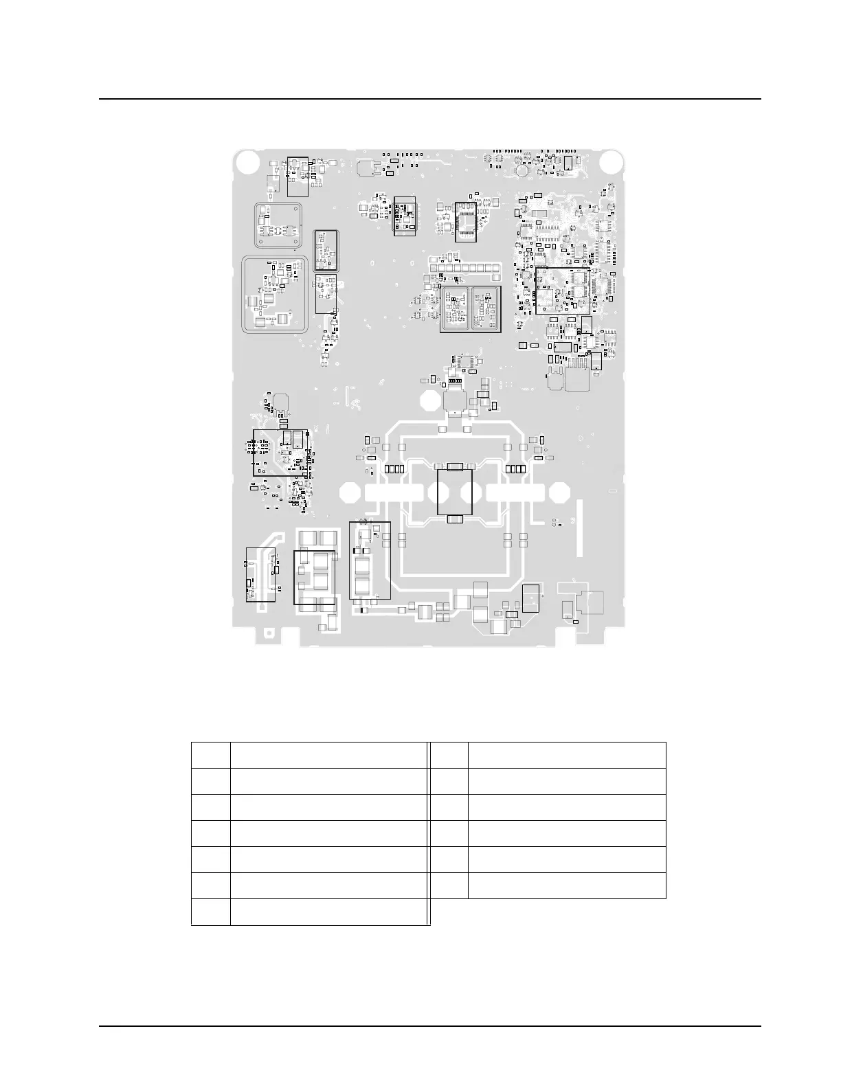
Figure 3-4. XTL 5000 Main Board Sections (VHF High Power)Side 2
Table 3-4. XTL 5000 Main Board Sections (VHF High Power)Side 2
3 RX Back-End 16 Antenna Switch
5 IF Filter 17 Rear Connector (J0402)
6 Controller Section 18 RX Front-End Biasing
12 TX PA 19 RX VCO Injection Stage
13 TX Power Control 20 TX VCO Injection Stage
14 Power Detector 21 FGU (Synthesizer)
15 Harmonic Filter
5
19
3
21
20
6
13
12
15
14
16
18

Table of Contents

Other manuals for Motorola ASTRO Digital XTL 5000

Questions and Answers:

Question and Answer IconNeed help?

Do you have a question about the Motorola ASTRO Digital XTL 5000 and is the answer not in the manual?

Motorola ASTRO Digital XTL 5000 Specifications

General IconGeneral
BrandMotorola
ModelASTRO Digital XTL 5000
CategoryRadio
LanguageEnglish

Related product manuals