May 25, 2005 6881096C74-B
3-6 Theory of Operation: Main Board Major Sections
3.2.2 UHF Range 1 (380-470 MHz) and UHF Range 2 (450-520 MHz) Band
The illustrations (Figure 3-5 on page 3-6 to Figure 3-8 on page 3-9) and their accompanying tables
(Table 3-5 on page 3-6 and Table 3-8 on page 3-9) identify the location of the major sections of the
main board.
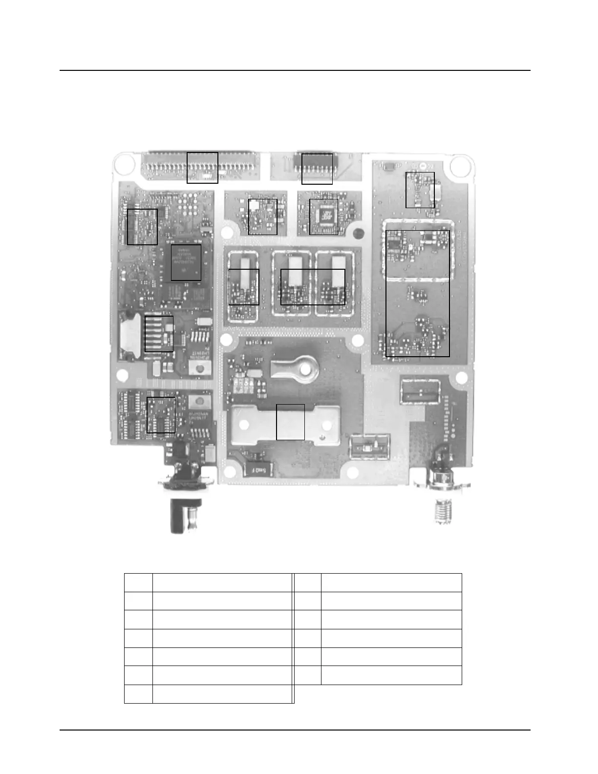
Figure 3-5. XTL 5000 Main Board Sections (UHF Range 1 Mid Power and UHF Range 2)—Side 1
Table 3-5. XTL 5000 Main Board Sections (UHF Range 1 Mid Power and UHF Range 2)—Side 1
1 Secure Connector (J0501) 8 Controller Section
2 Front Connector (J0401) 9 Audio Power Amplifier (PA)
3 RX Back-End (ABACUS III) 10 RX VCO
4 16.8 MHz Reference Oscillator 11 TX VCO
5 IF Filter 12 TX PA
6 RX Front-End 13 TX Power Control
7 Daughtercard
1
2
34
5
6
7
8
9
10
11
12
13
49
50
1
2
1
2
19
20

 Loading...


