May 25, 2005 6881096C74-B
3-70 Theory of Operation: Controller Section
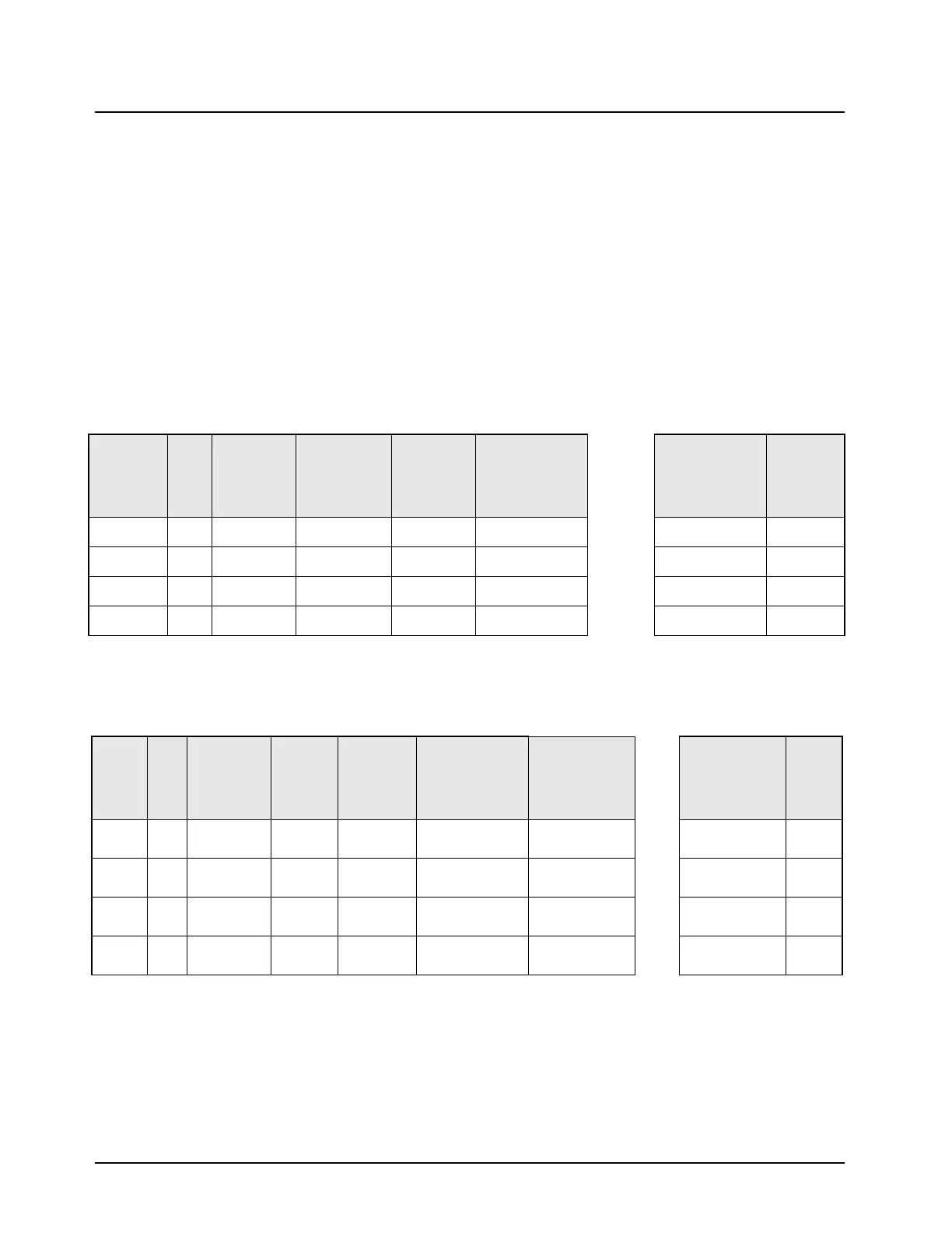
This radio meets EIA compatibility with external data accessory devices. The naming scheme (see
Table 3-14 and Table 3-15) used for the microcontroller's RS-232 lines sometimes conflict with EIA
RS-232 naming schemes. This is due to the microcontroller's pin names versus I/O direction,
compared to the EIA pin names versus I/O direction. Therefore, a matching naming scheme has
been developed. If the pin is coming from the UART, the pin name has UART in the name. However,
if you want to know how the EIA standard identifies the pin, a chart exists that provides the naming
conversion. The shipping rear data cable automatically routes the pins according to the EIA
standard, so interfacing to external data devices, such as computers, is done correctly. The naming
scheme information is only needed when the rear connector is opened and the wires need to be
identified for connection to a custom device. Note that the correct interfacing of RS-232 lines is
"output line" to "input line". For example, the TX pin of one device connects to the RX pin of the other
device, and the RTS pin of one device connects to the CTS pin of the other device. Never connect
TX to TX, RX to RX, and so on.
Table 3-14. Rear Connector Naming Scheme
Radio Pin
Direction
J2
Pin
No.
J2 Pin Name
Pin Alternate
Name
EIA-
Compatible
Name at
Rear Conn.
J2
P2 Rear
Accessory Cable
DB9 (Female) =
DCE Interface
DB9 (Male) Serial
Port Connector =
DTE Interface
Data
Device Pin
Direction
Output 4 UARTA_TX No Change TX_DCE TX_DCE = pin 2
<-->
pin 2 = RX_DTE Input
Input 5 UARTA_RX No Change RX_DCE RX_DCE = pin 3
<-->
pin 3 = TX_DTE Output
Output 10 UARTA_CTS Becomes RTS RTS_DCE RTS_DCE = pin 8
<-->
pin 8 = CTS_DTE Input
Input 11 UARTA_RTS Becomes CTS CTS_DCE CTS_DCE = pin 7
<-->
pin 7 = RTS_DTE Output
Note: Connecting to a computer = DTE device
TX to RX and RTS to CTS
Table 3-15. Remote-Mount Interconnect Board Connector Naming Scheme
Radio
Pin
Direc-
tion
J6
Pin
No.
J2 Pin Name
Pin
Alternate
Name
EIA-
Compatible
Name at
Rear Conn.
J2
P2 Rear
Accessory Cable
DB9 (Female) =
DCE Interface
HKN6122 Data
Cable DB9
(Female) = DCE
Interface
DB9 (Male)
Serial Port
Connector =
DTE Interface
Data
Device
Pin
Direc-
tion
Output 2 RS232_RXD Becomes
TX
TX_DCE pin 2 = TX_DCE TX_DCE = pin 2
<-->
pin 2 = RX_DTE Input
Input 3 RS232_TXD Becomes
RX
RX_DCE pin 3 = RX_DCE RX_DCE = pin 3
<-->
pin 3 = TX_DTE Output
Output 17 RS232_CTS Becomes
RTS
RTS_DCE pin 17 = RTS_DCE RTS_DCE = pin 8
<-->
pin 8 = CTS_DTE Input
Input 4 RS232_RTS Becomes
CTS
CTS_DCE pin 4 = CTS_DCE CTS_DCE = pin 7
<-->
pin 7 = RTS_DTE Output
Note: Connecting to a computer = DTE device
TX to RX and RTS to CTS

 Loading...


