6881096C74-B May 25, 2005
Theory of Operation: Controller Section 3-75
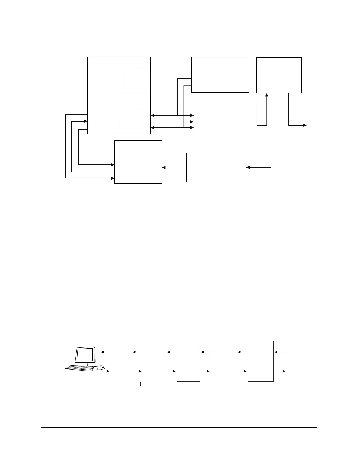
Figure 3-50. XTL 5000 TX Signal Path
After the DSP has finished its processing, filtering, and signaling on the audio data samples, it then
sends this data to the modulation DAC (U0900) on the BBP SSI port, where it is converted to the
analog modulation signal. The data is clocked over to the modulation DAC at a 2.4 MHz bit rate, with
a frame sync (representing the transmit data sample rate) of 48 kHz. Both of these clocks are
generated by the Urchin IC (U0901).
The modulation DAC audio output signal is sent to a switched capacitor low-pass filter (FL0900) that
performs anti-aliasing filtering. The filter output is sent through a multiplexer switch, U0902, and
finally on to the FGU/LV Frac-N synthesizer for modulation of the RF carrier signal.
3.8.12 Flash Programming
When the radio needs new program code, this can often be done by reflashing the FLASH ROM
(U102) located on the daughtercard. Reflashing is accomplished by using a programming cable
(HKN6155 for Mid Power or HKN6183 for High Power) and the Motorola Customer Programming
Software (CPS) FLASHport tool. The technique to flash the radio is the same as when using CPS or
the TUNER software to change features on your radio. Two data lines are utilized on the
programming cable to allow the computer to communicate with the microcontroller. These two lines
are called BOOT TX (J0401-25), and BOOT RX (J0401-26) (see Figure 3-51).
Figure 3-51. Boot RX and Boot TX Data Lines
Patriot
U100
SPI
SAP
BBP
CODEC
U0200
URCHIN Clock
IC
U0901
Modulation DAC
U0900
Gain/Attenuation
Stages (U0201, U202)
Low Pass Filter
FL0900
MODIN
MIC_HI
SCKA
SRDA
SCKA
SCKB
STDB
SC2B
S PI_SC
SPI_MOSI
SPI_MISO
MCLK
DT
FSR
TG
2.4MHz
MOD Data
48kHz
SCK
STD
SFS
FM OUT
Input
Output
(To LV FRACN)
(J0401-4)
512kHz
TX Data
8kHz
48kHz
2.4MHz
MAEPF-27890-O
Computer
(male) pin 2
(RX_DTE)
Computer
(male) pin 3
(TX_DTE)
9 pin cable
(female) pin 2
(TX_DCE)
9 pin cable
(female) pin 3
(RX_DCE)
Tout
14
13
Rin
Tin
11
12
Rout
RS232 IC
10 pin cable
(female) pin 10
(TX_DCE)
10 pin cable
(female) pin 2
(RX_DCE)
Controlhead
plug P104
or
Remote Mount
faceplate
plug P506
Boot_TX
Boot_RX
MAEPF-27815-O
HKN6155

 Loading...


