Interconnect Boards Schematics, Component Location Diagrams, and Parts Lists: Remote Interconnect Board (High Power Only) 8-21
6881096C74-B May 25, 2005
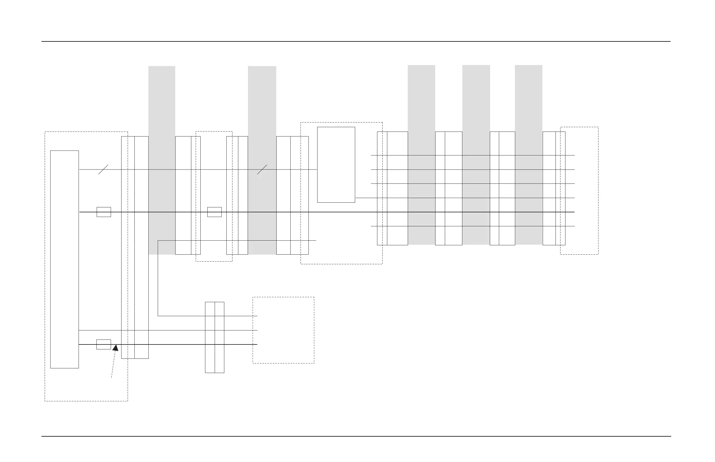
8.6 Motorcycle Signal Routing
Figure 8-9. Motorcycle Signal-Routing Diagram
Mic Hi
Gnd
Spkr +
PTT 1
Hub 1
Spkr -
31
JU512
16
20
15
13
12
8
7
6
6
5
4
3
2
1
23
16
18
1, 14
26
11
Hub
8
Hub
18
VIP out 1 12V
JU14
33
JU6
4
Vip In 3
Vip Out 2
Vip In 1
17
19
3
Hub 2
PTT 2
25
35
Mic Hi
12
6
2
4
Mic Hi
Potato
Mic with
DB9
Mic Hi
Motorcycle
Control Head
HC05
uP
sb9600
sb9600
Aux PTT
INTO
Aux
Mic
19, 21
23, 25
29
24
16
MAEPF-27906-O
1, 2, 14,
31, 32
Patriot
uP
Motorcycle
Remote
Cable
Motorcycle
Interconnect
Board
Millennium
Remote
Mount
Flex
Millennium
Control
Head
50-pin
J401
Millennium
VOCON
Board
Millennium
26-pin
D Rear
Accessory
AS+
DB15 to
Millennium
DB26
Adapter
AS+
15-pin
Rear
Accessory
Motorcycle
Kit
J2000
6-pin
Molex
Handlebar/
Headset
Rear
Accessory
Header
J402
Rear
Accessory
Flex
DB25
Control
Head
Connector
J5 P502
28-pin
Control
Head
Header
J103
DB9
Microphone
Connector
J3
PTT 1 - Detected by radio via INTO.
HUB 1 - Detected by control head or HUB input. Sent to radio via sb9600.
PTT 2 - Detected by control head on Vip In 1. Sent to radio via sb9600.
HUB 2 - Detected by control head on Vip In 3. Sent to radio via sb9600.

 Loading...


