6881096C74-B May 25, 2005
Troubleshooting Charts: Troubleshooting Tables 5-11
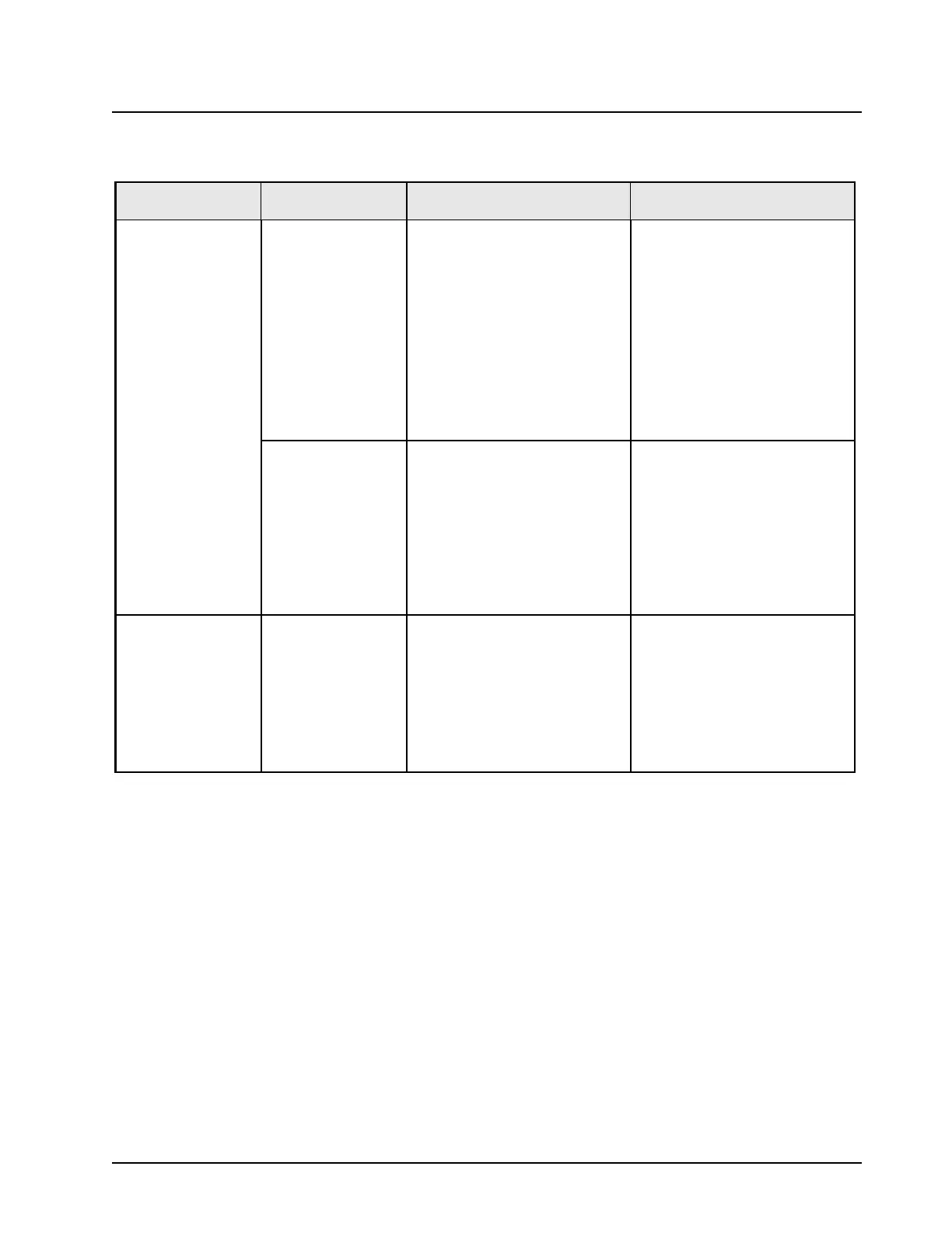
Table 5-4. XTL 5000 Receiver Troubleshooting Table (VHF Band)
Symptom Check Section Troubleshooting Procedure Component
Poor Sensitivity Front-end • Check 2.85 V on pin 4 and 0 V
on pin 5 of U3250
• U3250.
• Check transistors Q3250,
Q3252 VCE levels. Levels
should be
~ 5 V
• Q3250, Q3252 (only Q3252 in
STD mode).
• Using a RF probe, check for 20
dBm on TP6771
• FGU section.
• Verify that all Front-end
components are well soldered
• Visual inspection of soldering.
Back-end • Check for VCE level of 8 V at
IF amplifier
• Q3401.
• Verify that ABACUS is well
soldered
• Visual inspection of U3000
leads soldering.
Check ABACUS for:
• Reference clock 16.8 MHz
• Synthesizer frequency
107.4 MHz or 111.9 MHz
• R3822.
• C3846.
Poor Reception Back-end Check ABACUS DC voltages:
• 2.7-3 V on pins 1, 2, 6, 9, 14,
17, 40
• 5 V at on 39
• U3000.
• Check Second Local Oscillator
for voltage of 0.5-4.7 V
• U3000 pin 38.
• Check second IF for 2.25 MHz • C3047.

 Loading...


