May 25, 2005 6881096C74-B
4-6 Troubleshooting Procedures: VHF (136–174 MHz) Band Main Board Troubleshooting
2. To determine if the "out-of-lock" is frequency or VCO dependant, place the unit into RF TEST
Mode, as described in the ASTRO Digital XTL 5000 VHF/UHF Range 1/UHF Range 2/700–
800 MHz Mobile Radio Basic Service Manual (6881096C73) and step through each test
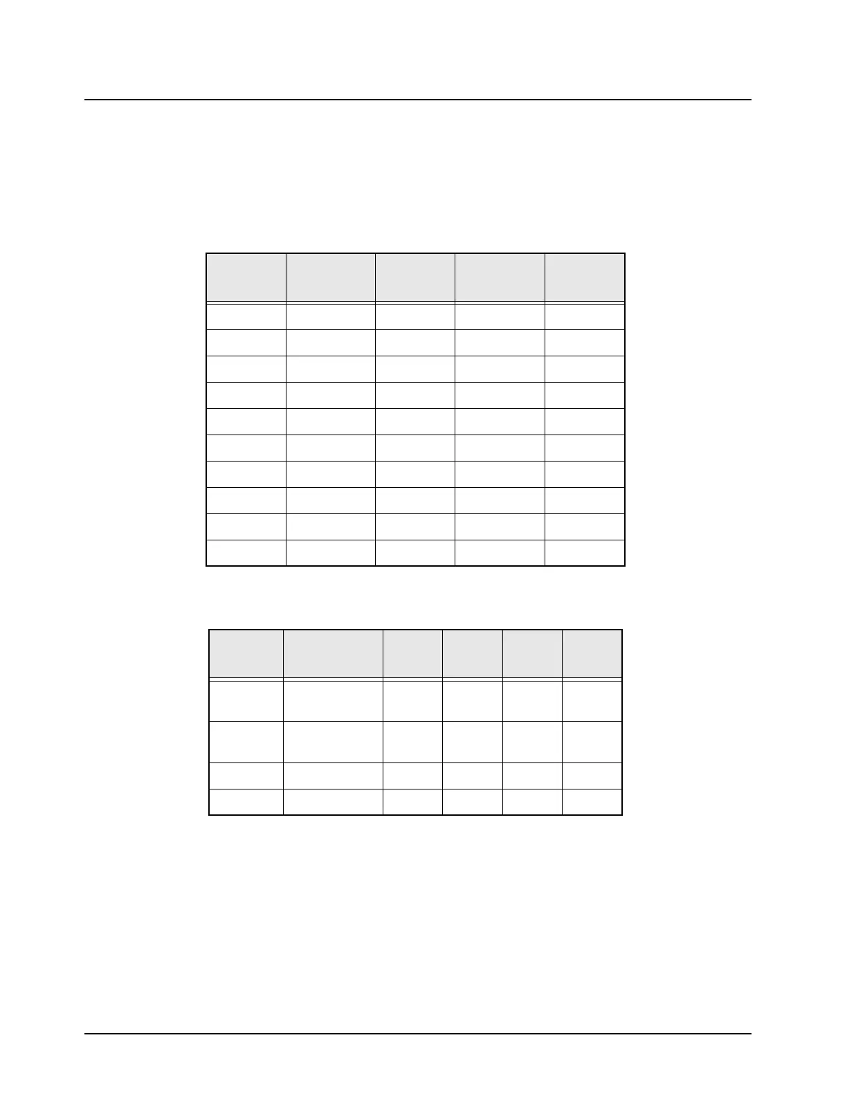
channel. Table 4-3 indicates the frequency and Aux logic level for each test mode channel. In
addition, Table 4-4 provides information about the frequency of operation for each VCO.
3. Continue troubleshooting by using the Fail 001 troubleshooting chart in Chapter 5.
4.6.2 VCO Hybrid Assembly
The VCO hybrid substrate is glued to the carrier board. The hybrid is not a field-repairable assembly.
If a failure is indicated in this assembly, replace the entire carrier board.
Table 4-3. Test Mode Channels
Test
MODE
LV Frac-N
TX Logic
TX Freq
MHz
LV Frac-N
RX Logic
RX Freq
MHz
CHAN 1 AUX 2 136.0125 AUX 3 245.7125
CHAN 2 AUX 2 140.7625 AUX 3 250.4625
CHAN 3 AUX 2 145.5125 AUX 3 255.2125
CHAN 4 AUX 2 150.2625 AUX 3 259.9625
CHAN 5 AUX 2 154.9875 AUX 3 264.5875
CHAN 6 AUX 1 155.0125 AUX 4 264.7125
CHAN 7 AUX 1 159.7625 AUX 4 269.4625
CHAN 8 AUX 1 164.5125 AUX 4 274.2125
CHAN 9 AUX 1 169.2625 AUX 4 278.9625
CHAN 10 AUX 1 173.9875 AUX 4 283.5875
Table 4-4. VCO Frequency and Switching Logic
MODE
Frequency
(MHz)
AUX1 AUX2 AUX3 AUX4
RX 245.65–
264.65
LOW LOW HIGH LOW
RX 264.65–
283.65
LOW LOW LOW HIGH
TX 155–174 HIGH LOW LOW LOW
TX 136–155 LOW HIGH LOW LOW

 Loading...


