May 25, 2005 6881096C74-B
4-32 Troubleshooting Procedures: Standard Bias Tables
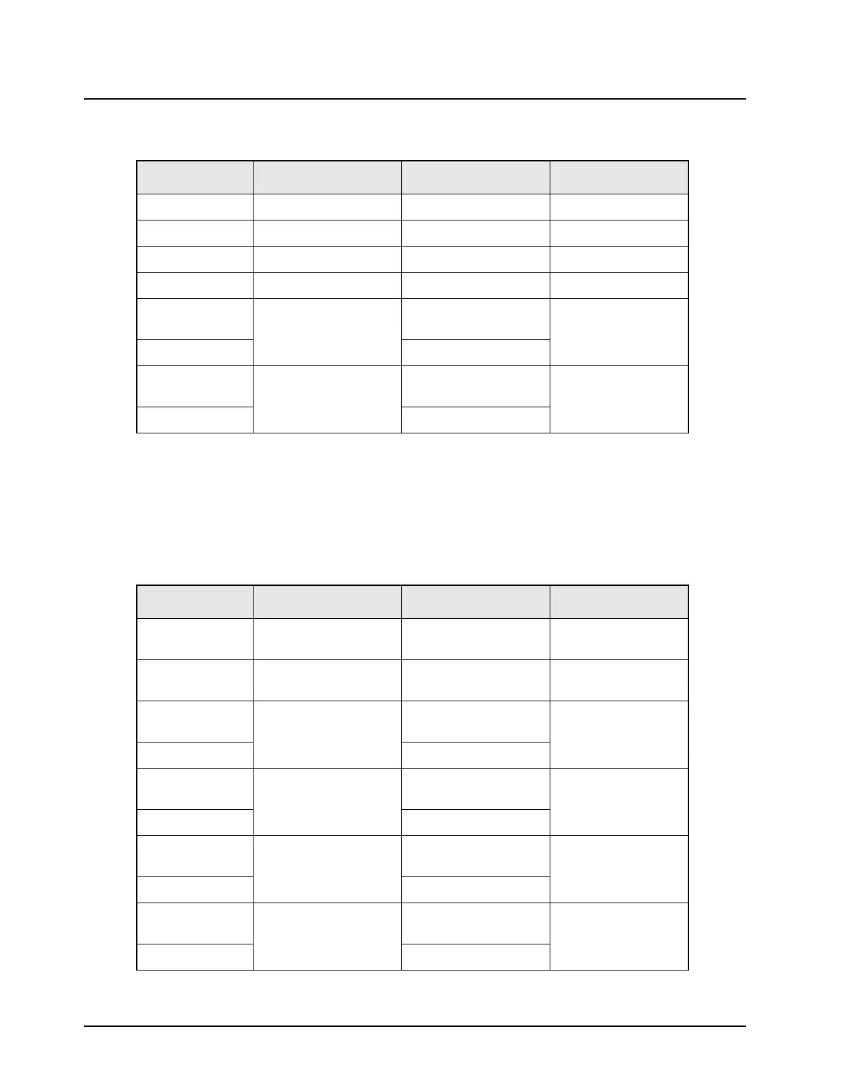
Table 4-19. Standard Operating Bias: VIP Lines (Dash Configuration)
Nominal Value Signal Name Range/State Probe Locations
NA VIP_OUT_1_5v Not accessible J0401-13
NA VIP_OUT_2_5v Not accessible J0401-14
NA VIP_IN_1_5v Not accessible J0401-15
NA VIP_IN_2_5v Not accessible J0401-16
SW_B+ level VIP_OUT_1_12v Deactivate = relay
closed
J0401-11, J2-18
0.3 V to 0.5 V Activate = relay open
SW_B+ level VIP_OUT_2_12v Deactivate = relay
closed
J0401-12, J2-19
0.3 V to 0.5 V Activate = relay open
Note: The voltage levels on the microprocessor side are at 2.85 V levels. The microprocessor is
not designed to drive the relay, but instead, is intended to drive the transistors inside the control
head or on the interconnect board. Be careful when changing jumpers.
Note: The impedance of the relay is why the SW_B+ does not damage the VIP line. Never connect
SW_B+ directly to a VIP line.
Table 4-20. Standard Operating Bias: VIP Lines (Standard Remote Configuration)
Nominal Value Signal Name Range/State Probe Locations
VIP_OUT_1_5v Access only by custom
pin-out
J0401-13
VIP_OUT_2_5v Access only by custom
pin-out
J0401-14
5 V VIP_IN_1_5v Idle = deactivate = 5 V
bias
J0401-15
0 V Activate = ground
5 V VIP_IN_2_5v Idle = deactivate = 5 V
bias
J0401-16
0 V Activate = ground
SW_B+ level VIP_OUT_1_12v Deactivate = relay
closed
J0401-11, J2-18
0.3 V to 0.5 V Activate = relay open
SW_B+ level VIP_OUT_2_12v Deactivate = relay
closed
J0401-12, J2-19
0.3 V to 0.5 V Activate = relay open
Note: VIP_IN programmed by CPS. Requires custom pin-out to gain access.

 Loading...


