6881096C74-B May 25, 2005
Troubleshooting Procedures: Standard Bias Tables 4-31
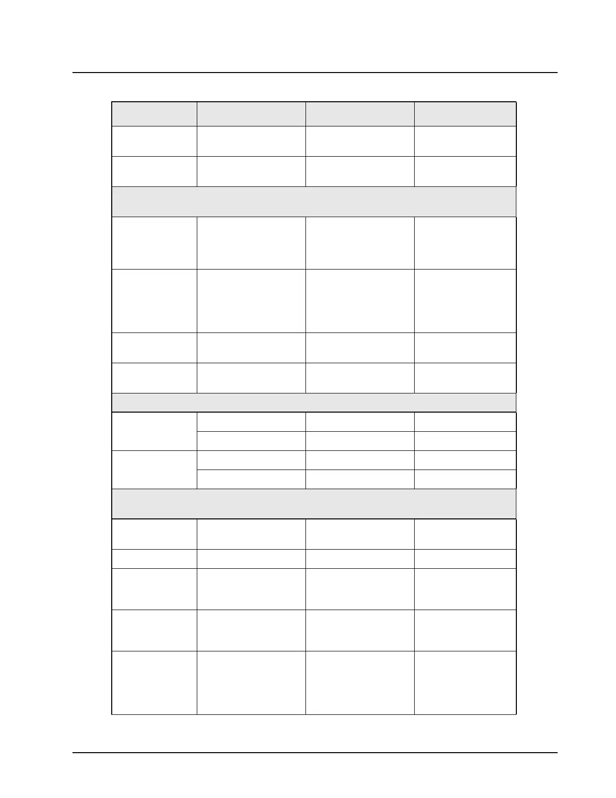
9.2 V Mic_Hi When microphone
disconnected
TP0402, J0401-4
13 V to 16 V Mic_Hi When programming
cable inserted
TP0402, J0401-4
Note: Do not press the PTT unless the PCB is inside a chassis even for a moment to check a line.
Permanent RF hardware damage can occur to the board due to no heatsinking.
9.2 V Aux_Mic = [ A(tx) ]
(transmit audio)
Expects 300 mV input
(APCO default)
Expects 80 mV input
(motorcycle use)
J0401-6, J2-23
2.84 V Aux_PTT = [ PTT ] Idle = High
Active = Low
Hard-wired PTT, which
will mute or unmute
Aux_Mic line
J0402-24, J2-16
1.4 Vdc to 25 Vdc
(needs ext. cap)
Aux_TX (audio input) 300 mV line-level
(no mic bias)
J0401-7
0 V Aux_RX (audio input) 300 mV line-level
(Audio PA In)
J0401-8
Note: The Mic_Hi audio overrides Aux_TX/Aux_Mic audio, and the speaker is always muted.
0 V Speaker + Muted (output) J2-21, U204-4
Speaker - Muted (output) J2-20, U204-6
26v peak-to-peak
@volume= 15+
Speaker + Unmuted (output) J2-21, U204-4
Speaker - Unmuted (output) J2-20, U204-6
Note: Never ground speaker lines. They are differential, not single-sided.
Use an oscilloscope probe on "Spk+" and oscilloscope-probe GND on "Spk-".
2.85 V Monitor Idle = High
Activate = Low
J2-22
2.84 V Audio_PA_Enable Q0200-1
1.3 V RX_Filt_Audio = [A(rx) ]
(receive audio/audio
output)
300 mV line-level output J2-21, TP0204
0 V or 5 V Chan_Act = [A(p) ]
(qualified audio
presence)
Idle = Low (0v)
Active = High (5 V)
J2-13
HUB This pin causes the
control head to send
SB9600 message to the
radio, indicating when
HUB is attached
P502-3
Note: Do not KEY UP unless the board is inside a chassis.
Table 4-18. Standard Operating Bias: Audio Lines (Continued)
Nominal Value Signal Name Range/State Probe Locations

 Loading...


