9-38 MTR3000 Radio Frequency Distribution System (RFDS) Equipment: Field Tuning Procedures
4. Do not change the settings on the network analyzer, just repeat Step 1, 2, and 3 for the other
LO cavities 2 and 3 on the left.
9.5.2.2.3 Tuning the HI side
1. Connect the two N-type test cables hooked up on the ports 1,2 of the NWA to the two N type
female connectors of HI cavity 4. Set up markers on the NWA-Marker 1 to HI Frequency on
CH2 (S21–Transmission) and Marker 2 to LO Frequency on CH1 (S22–Reflection).
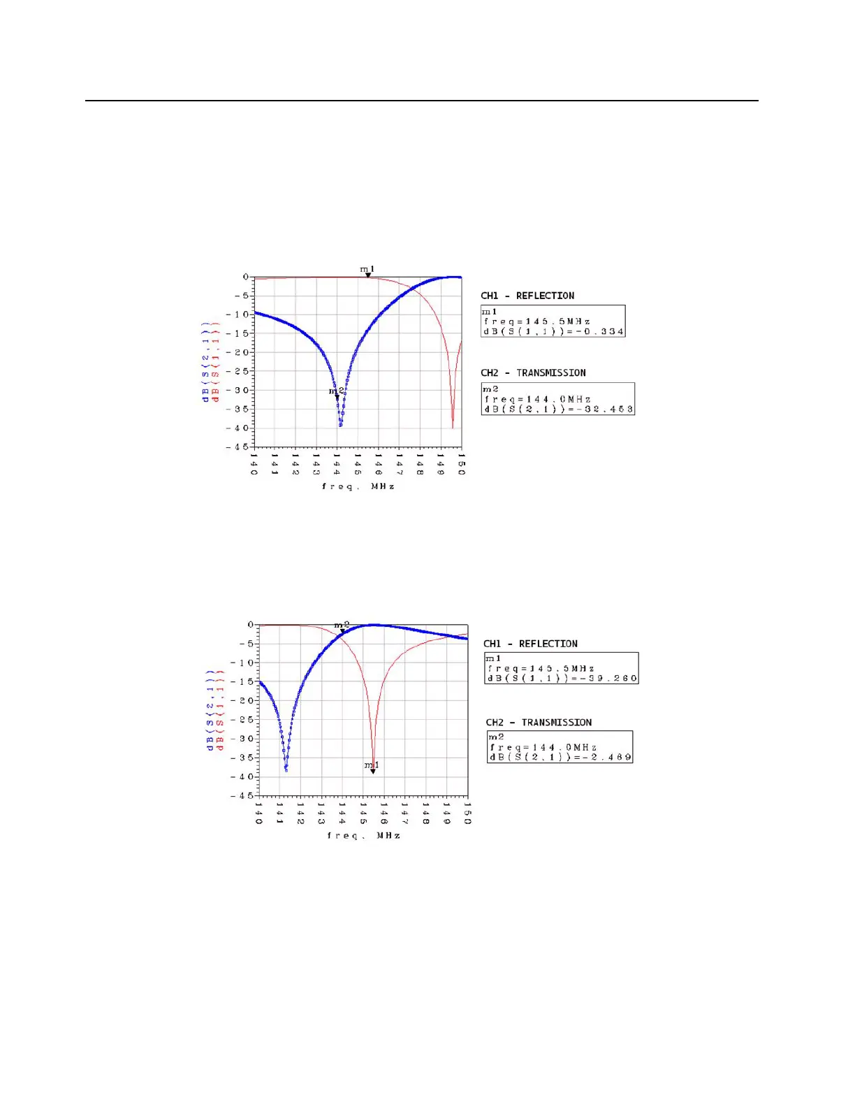
Figure 9-31 Untuned HI SIDE–Cavity 4
2. Turn the notch screw until Marker 1 falls in the dip of the CH1 curve as shown in Figure 9-32.
Lightly tighten the locknut in place to prevent further movement.
Figure 9-32 Tuned CH1 - HI SIDE–Cavity 4
3. Turn the pass screw until Marker 2 falls in the dip of the CH2 curve as shown in Figure 9-33.
Lightly tighten the locknut in place to prevent further movement.
 Loading...


