MTR3000 Radio Frequency Distribution System (RFDS) Equipment: Field Tuning Procedures 9-39
Figure 9-33 Tuned CH1, CH2 - HI SIDE–Cavity 4
4. Do not change the settings on the network analyzer, just repeat Step 5, 6, and 7 for the other
HI cavities 5 and 6 on the right.
9.5.2.2.4 Fine Tuning the Duplexer
1. When all 6 cavities have been tuned separately, connect the Port 1 NWA cable to the N con-
nector of the LO side input cavity (cavity 1) and the Port 2 of NWA to the duplexer Antenna
port (ANT) respectively.
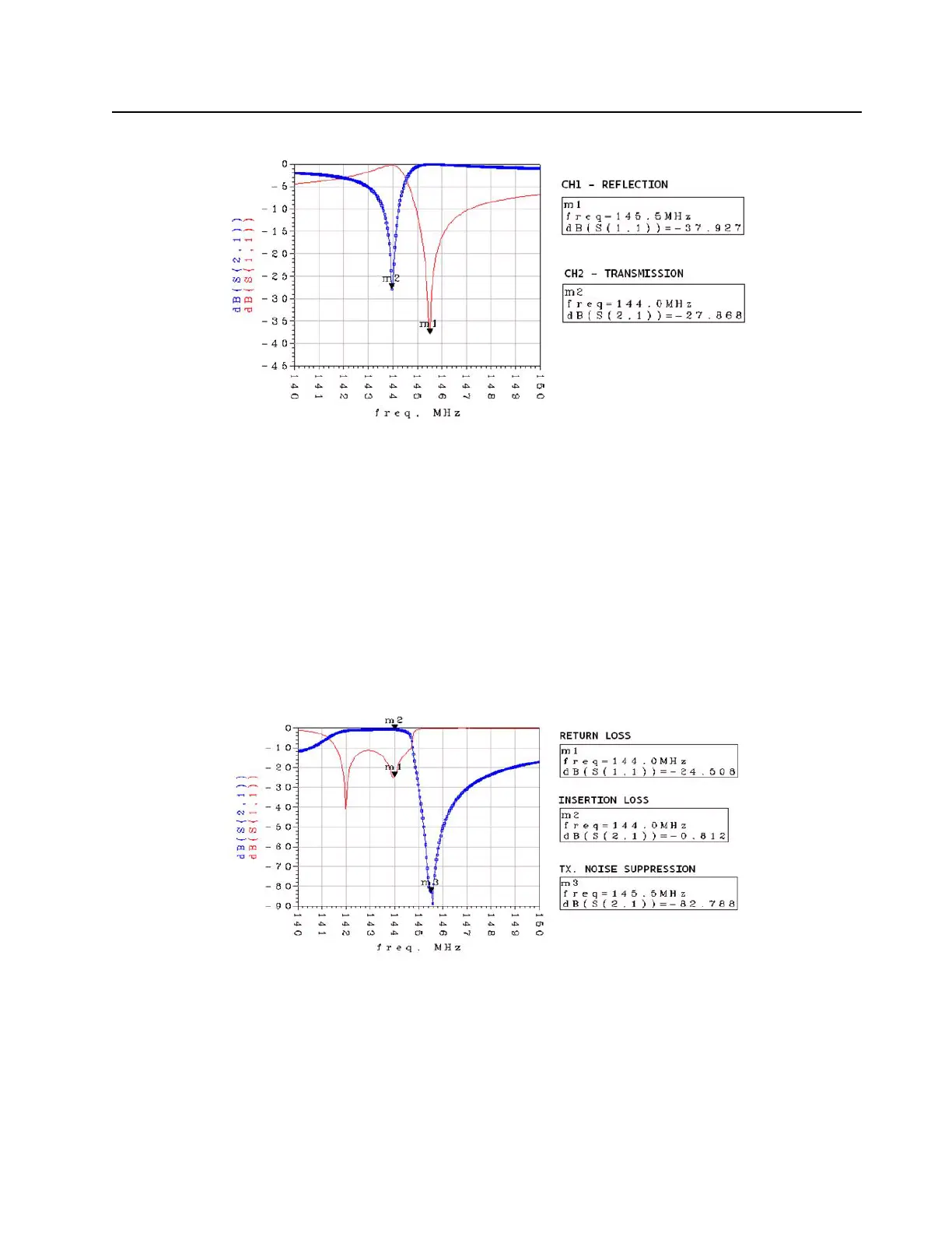
a. Connect ports 1 and 2 of the NWA to the LO input side (far left) and ANT, respectively. The
desired response on the NWA for m1 (return loss), m2 (insertion loss), and m3 (noise
suppression) is as shown in Figure 9-34.
Figure 9-34 LO Side Response Curves
b. Now connect ports 1 and 2 of the NWA to the ANT and the HI input side (far right),
respectively. The desired response on the NWA for the m1 (return loss), m2 (insertion
loss), and the m3 (noise suppression) markers is as shown in Figure 9-35.
 Loading...


