MTR3000 Maintenance and Disassembly/Reassembly: Disassembly and Reassembly – Detailed 14-7
6. Position the fan on the casting and position the fan grill over the fan.
7. Secure the fan to the Power Supply casting with the four screws or PA casting with the five
screws.
8. Orient the connector as before and push the power connector into the plug on the casting.
9. Restore power to the base station/repeater and ensure the fan runs briefly at power-on.
14.7.2.2 Power Amplifier Module
1. Make sure the base station/repeater power is turned off at the breaker to the AC or DC
source.
2. Remove the base station/repeater from the rack or cabinet.
3. If the base station/repeater is equipped with an External Preselector, label and disconnect the
corresponding RF coax cables to the Preselector and remove the screws securing the
Preselector to the base station/repeater.
4. Remove the two screws securing the battery backup connector to the PA casting.
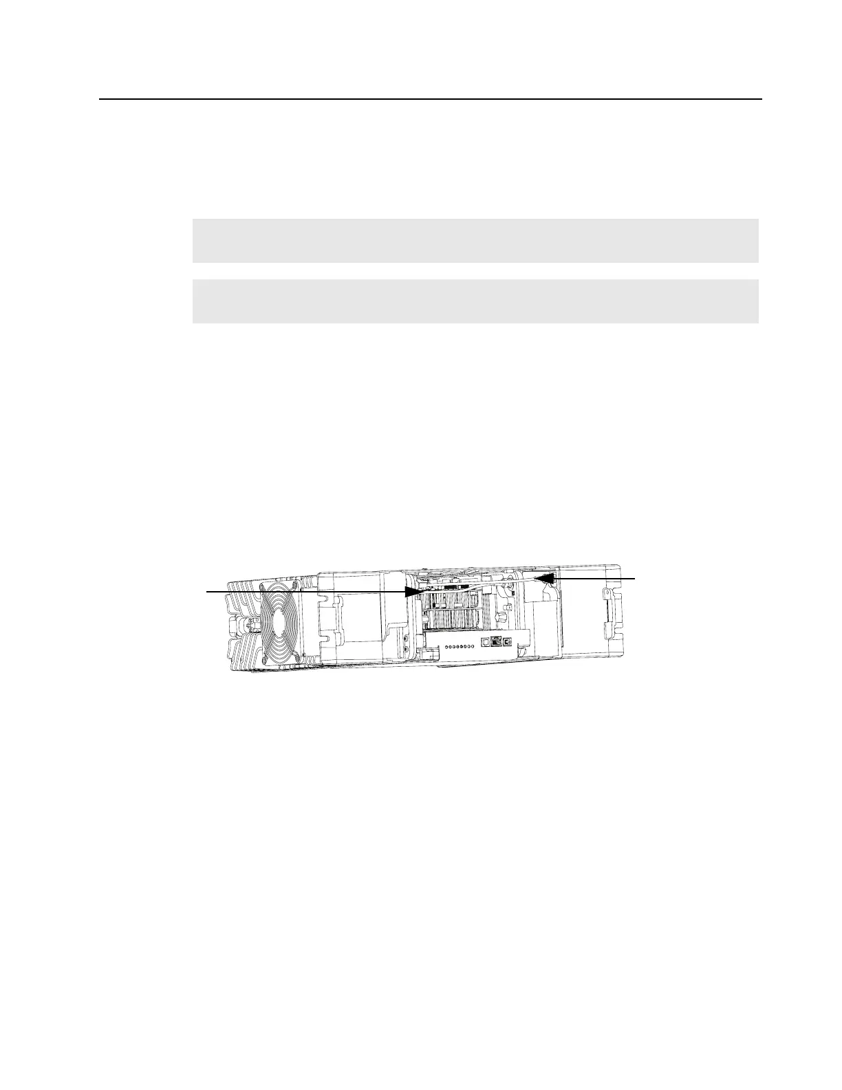
5. Disconnect the Exciter-to-PA coaxial cable from the PA module (Refer to Figure 14-4) by
pushing in on the outer ring and turning.
Figure 14-4 Removing two cables from the front
6. Remove the six screws securing the top and bottom plates to the PA Cover.
7. Ensure that the correct PA Module is being installed.
8. Install the replacement PA Module.
9. Line up holes in the PA cover with the corresponding holes in the top and bottom plates.
10. Secure the PA Module to the casting with the six screws.
11. Reconnect all cables.
12. Secure the battery backup connector to the PA casting.
13. Replace the optional Preselector with the two screws and reconnect the cables.
14. Restore power to the base station/repeater.
Note
The PA and PS fans have different fan terminations. The PA fan has a fifth screw to
terminate its ground wire.
Note
When the PA fan is replaced, it is recommend to replace the PS fan as well since the PS fan
is not alarmed upon its failure.
Exciter-to-PA
Coaxial Cable
Rx Input Cable
 Loading...


