CAUTION
• BATTERY PACK
PART
NUMBER
65-20404
65-10266
FUSE
3A
lOA
OPERATION
1101220
VAC
12
VDC
Attach the battery pack
to
the Analyzer's rear panel
with 2 clips and 2 screws. Align and slide the pack's
mounting clips into the slots on the mounting brackets
On
the left side. Align the captive screws with the
mounting holes
on
the right side
and
tighten them. Con-
nect the power plug to the connector at the
top
right
of
the rear panel.
Remove accessories from the cover
as
needed. Insert the
whip antenna into the Antenna port located in the
Duplex Generator section
of
the front panel. Pull the
Antenna control located in the RF SECTION.
Turn
POWER switch, located on the front panel, to the On
position. When the Oven Ready indicator illuminates,
the frequency standard stabilizes and the Analyzer
is
ready for use instantaneously (with standard TCXO).
Before operating the Analyzer, carefully study the func-
tion and purpose
of
each control and feature. Become
familiar with the operating procedures described in this
manual.
When installing the Analyzer in a vehicle, fuse the DC
supply line close to the vehicle's battery. The DC-lOA
fuse, located
on
the Analyzer's rear pane!, protects it
against overload but does not protect the vehicle.
propriate connector on the Analyzer's rear panel. Con-
nect the cord's other end to the power source.
For
AC,
use a grounded 3-wire 100-130 VAC or 200-260 VAC
power source. On the back
panel's
two-position
LINE
switch, select either 110 or 220 position.
The
factory sets
the
LINE
switch, as ordered.
Units
ordered as
R-2001D/220 or R-2002D1220
will
be pre-set for 220
VAC and will have a 3.0A fuse installed. Install a 3A
fuse for
110
V
AC
operation and a
lOA
fuse for DC
operation.
ALL
OTHER
COUNTRIES:
MOTOROLA INC.
International Parts Dept.
Schaumburg,
IL
60196
U.S.A.
Phone; 312-576-6482
TWX:
910-693-0869
Telex:
722443
Cable: MOTOL PARTS
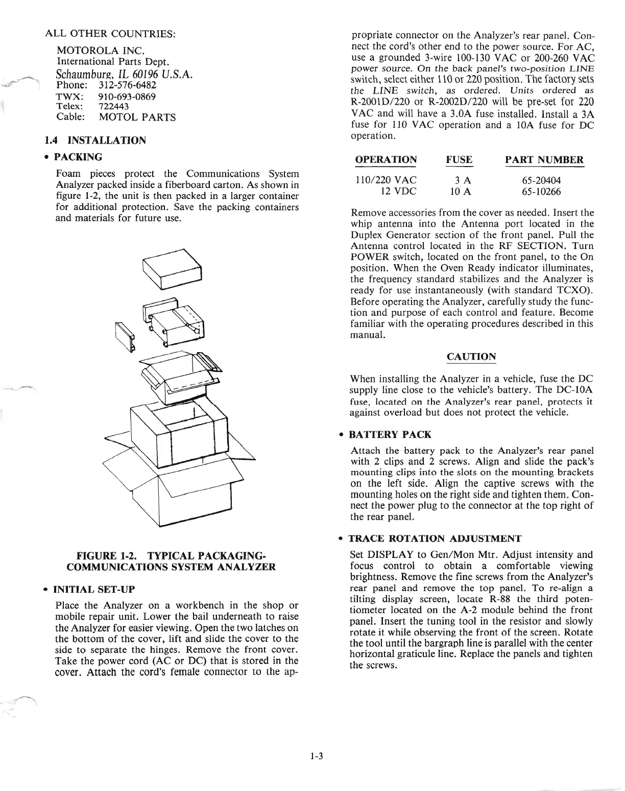
Foam pieces protect the Communications System
Analyzer packed inside a fiberboard carton.
As
shown in
figure 1-2, the unit
is
then packed in a larger container
for additional protection. Save the packing containers
and materials for future use.
1.4 INSTALLATION
• PACKING
FIGURE
1-2.
TYPICAL
PACKAGING-
COMMUNICATIONS SYSTEM ANALYZER
•
INITIAL
SET
-UP
Place the Analyzer on a workbench in the shop
or
mobile repair unit. Lower the bail underneath to raise
the Analyzer for easier viewing. Open the two latches
on
the bottom
of
the cover, lift and slide the cover
to
the
side
to
separate the hinges. Remove the front cover.
Take the power cord (AC
or
DC)
that
is
stored in the
cover. Attach the cord's female connector to the ap-
•
TRACE
ROTATION ADJUSTMENT
Set DISPLAY to
Gen/Mon
Mtr. Adjust intensity and
focus control to obtain a comfortable viewing
brightness. Remove the fine screws from the Analyzer's
rear panel and remove the top panel. To re-align a
tilting display screen, locate R-88 the third poten-
tiometer located
on
the
A-2
module behind the front
panel. Insert the tuning tool in the resistor and slowly
rotate it while observing the front
of
the screen. Rotate
the tool until the bargraph line
is
parallel with the center
horizontal graticule line. Replace the panels
and
tighten
the screws.
1-3

 Loading...

