TABLE 2-1. CONTROLS, INDICATORS, AND CONNECTORS
ITEM
RF SECTION:
DESCRIPTION
FRONT
PANEL
(figure 2-1)
FUNCTION
RFIn/Out
connector
RF Level Variable
control
RF Level Step
attenuator
Ext Wattmeter
DUPLEX
GEN
switch
Output
connector
Antenna
Port
Type N connector
Potentiometer
14-position ganged atten-
uator
and switch
Connector
Two-position toggle switch
BNC connector
Fused BNC connector
PN
#09-80378A51
RF input in monitor mode, RF
output
in generate mode.
Vernier control
of
RF
output
level. Pull for antenna port.
Push for
RF
In/Out
port. Exceeding the Am Limit marking
in
AM
generate mode may result in distorted output.
Ten dB per step control
of
RF
output
level in generate
mode. Also serves as RF input level step
attenuator
in
monitor and spectrum analyzer modes.
Allows input from Motorola ST-1200 series inline watt-
meter elements for measurement and
CRT
display
of
for-
ward and reflected transmitted power.
Select either
On
or
Off. Duplex
output
from
DUPLEX
port
is
enabled with switch On.
Output
connector for duplex generator
output.
Connector for the whip antenna.
FUSE REPLACEMENT PROCEDURE:
Place a male BNC connector
on
the
antenna
port. Use a
pair
of
slip-joint pliers to grab onto the knurled portion
of
the male BNC connector.
Turn
counterclockwise to loosen.
Unscrew the connector all the way,
off
the front panel. The
fuse
is
plugged into the female center pin. Use a needle-nose
pliers to remove the defective fuse and replace it with a 0.10
A mini-fuse,
PN
#65-80377A61.
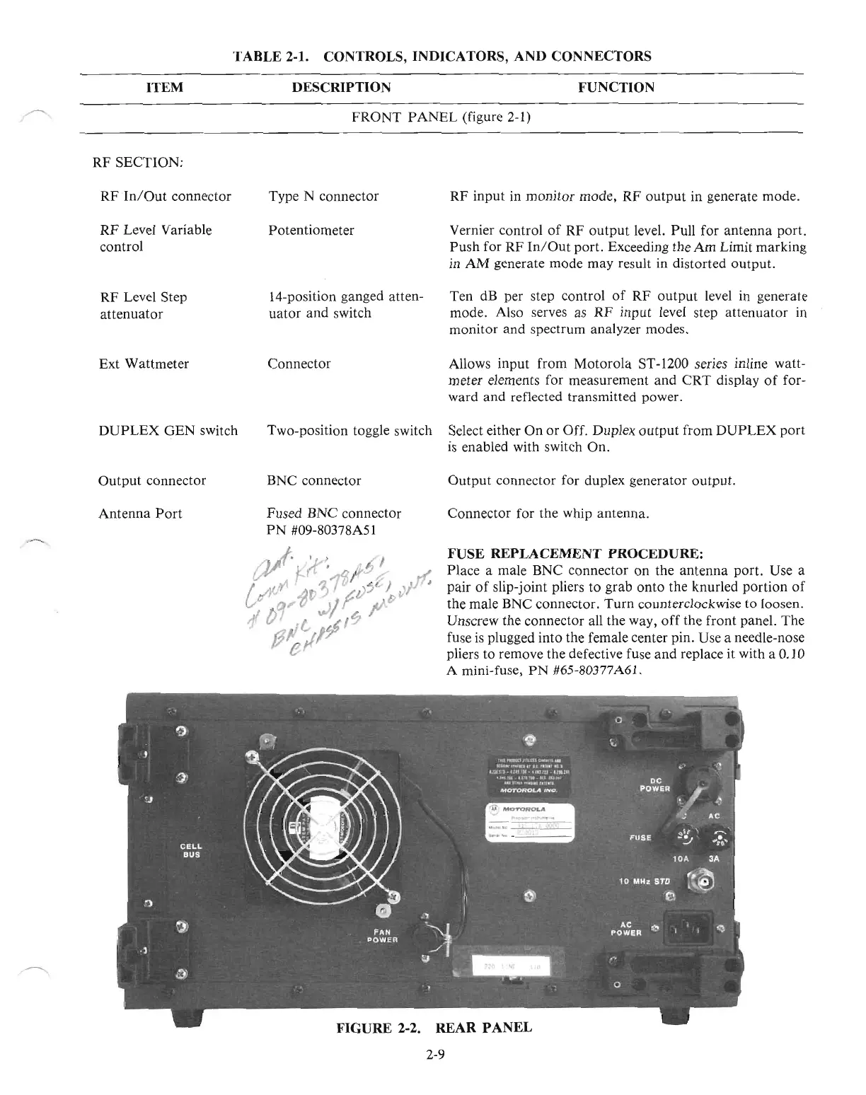
FIGURE 2-2. REAR
PANEL
2-9

 Loading...

