nels display a pair
of
frequencies for each channel
number, one for generate and one for monitor. Identify
generate
or
monitor frequencies by the letters RX
or
TX. The system changes automatically from transmit to
receive frequencies with the Generate/Monitor switch
or
the MIC push-to-talk switch. Each simplex channel
and
each generate frequency
of
a duplex channel has
either a
PL
or
DPL
code. A dash replaces an unused
code. When
a preset
is
selected, the appropriate
PL
or
DPL
code
is
also programmed into the signaling
generator.
• ENTRY WITH MEMORY TABLE
To
enter a frequency
or
code into the memory table,
proceed as follows:
1.
Select RF Memory DISPLAY position.
2. Use the keypad cursor keys to select the line and lo-
cation to be changed.
3. Use the keypad numeric keys to enter the new fre-
quency,
PL,
or
DPL
code.
4. Make other changes or corrections for each line
of
the memory table.
5.
Turn
the
POWER
switch to Standby for five sec-
onds.
Turn
the switch
On
and check the memory table
to verify
that
all information
is
correct.
• ENTRY WITHOUT MEMORY TABLE
To
enter a frequency
or
code without using the memory
table, proceed as follows:
1.
Select
Gen/Mon/Mtr
DISPLAY position.
2. Use the keypad cursor keys to locate the cursor over
the first digit in the frequency.
3. Use the numeric keys to enter a new frequency. The
new frequency displays automatically when the power
is
turned on.
4.
If
a frequency
is
selected from the memory table,
after a new frequency was entered directly, the frequen-
cy
from the memory table takes precedence and it will
appear when the Analyzer
is
turned
off
and one again.
5.
To
change
or
add
PL
or
DPL
codes in the generate
mode, use the same procedure but move the cursor to
the second line.
• PRESET TURN-ON
The Analyzer's normal internal configuration turns-on
at
Gen/Mon
Mtr, FM, and
PLiDPL.
To
program the
system to turn-on
at
any other configuration, proceed
as
follows:
1.
Press
an
arrow key to select the desired DISPLAY.
2. Press
an
arrow key to select the desired
FUNCTION.
3. Press a
MODULATION
key to select the desired
Code Synthesizer Mode.
4. Simultaneously depress both keypad cursor keys to
obtain the special function display. Enter code number
3-11
71
to enter the new configuration into the nonvolatile
memory.
5.
Turn
the
POWER
switch
off
and then on again.
Check the display's accuracy.
6.
To
restore the system to normal turn-on configura-
tion, follow steps
1 through 4 above.
• SIGNALING SEQUENCE
The complete signaling simulator in the system includes
both encode and decode tone sequence synthesizer
capability for the following
MODULATION
modes:
Fixed
1 KHz tone
Single tone variable
Private Line (PL)
Tone A
or
Tone B
Digital Private Line (DPL) sub-audible squelch
Two-tone sequential paging
5/6
tone paging
Select
V signaling
General sequential, ten-tone
Mobile telephone signaling
(lMTS) improved mobile telephone system
(MTS) mobile telephone system
2805
Hz
Tone Remote, base station
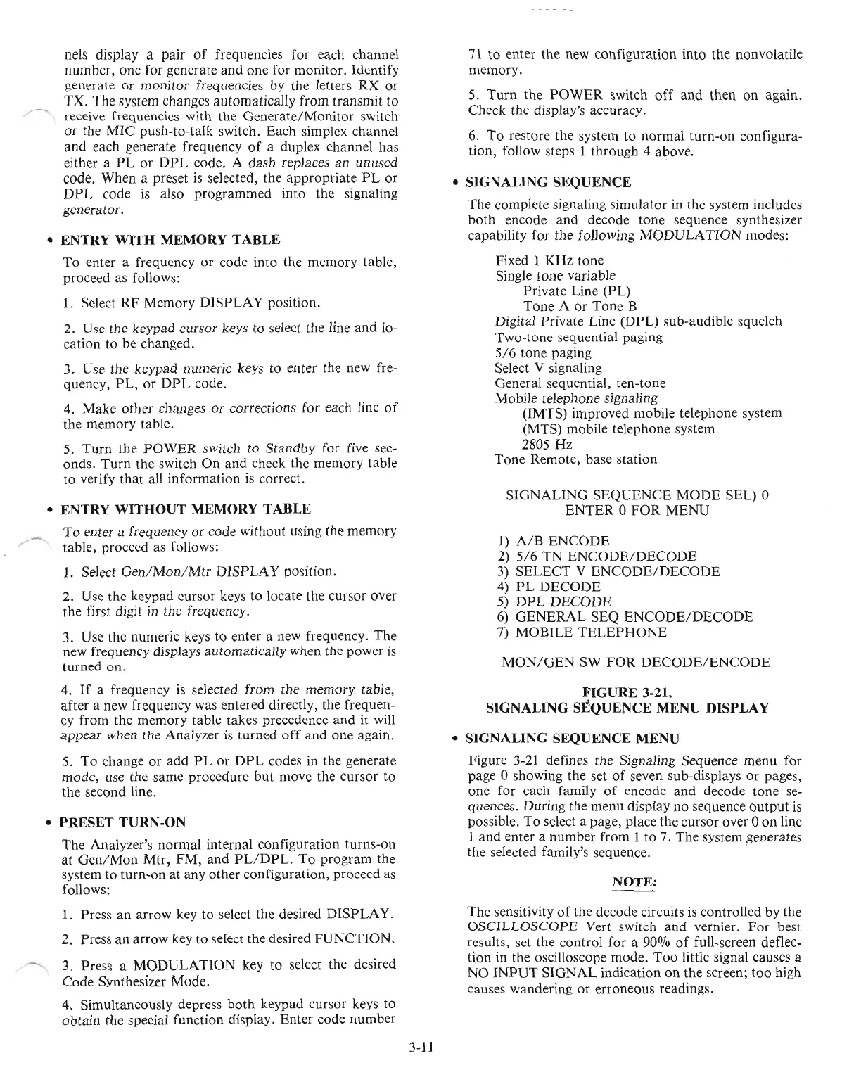
SIGNALING SEQUENCE
MODE
SEL) 0
ENTER
0
FOR
MENU
1)
A/B
ENCODE
2)
5/6
TN
ENCODE/DECODE
3)
SELECT
V
ENCODE/DECODE
4)
PL
DECODE
5)
DPL
DECODE
6)
GENERAL
SEQ
ENCODE/DECODE
7)
MOBILE
TELEPHONE
MON/GEN
SW
FOR
DECODE/ENCODE
FIGURE
3-2l.
SIGNALING SEQUENCE MENU DISPLAY
• SIGNALING SEQUENCE MENU
Figure
3-21
defines the Signaling Sequence menu for
page 0 showing the set
of
seven sub-displays
or
pages,
one for each family
of
encode and decode tone
se-
quences. During the menu display no sequence
output
is
possible. To select a page, place the cursor over 0
on
line
I and enter a number from I to 7. The system generates
the selected family's sequence. .
NOTE:
The sensitivity
of
the decode circuits is controlled by the
OSCILLOSCOPE
Vert switch and vernier.
For
best
results, set the control for a 90%
of
full-screen deflec-
tion in the oscilloscope mode.
Too
little signal causes a
NO
INPUT
SIGNAL indication
on
the screen; too high
causes wandering
or
erroneous readings.

 Loading...

