•
AUDIO
FILTERS
Table
3-4 lists
audio
filter characteristics.
Highpass:
5
Hz
5
Hz
300
Hz
3
KHz
Lowpass:
20
KHz
20
KHz
3
KHz
300
Hz
Filter
Char-
acter-
istic
Filter
Frequency
Mode (Not More
Than
0.5
dB)
Frequency
(Not
More
Than
3
dB)
300
Hz
3
KHz
3
KHz
300
Hz
Frequency
(At Least
20
dB)
170
Hz
1.7
KHz
40
KHz
5.4
KHz
540
Hz
•
MODULATION
In the frequency
MODULATION
DISPLAY
(figure
3-16), view the
composite
modulation
audio
waveform
in generate
mode
or
the demodulated
audio
in
monitor
mode.
Analyze waveforms
on
the scope
to
measure
deviation graphically. Use the
MONITOR
BW switch
to
select wide
or
narrow
bandwidth.
In the wide position,
adjust
frequency
modulation
level
from
a to 75
KHz
peak deviation. In
the
narrow
position,
adjust
the range
from
a
to
20 KHz.
The
display's vertical deflection is
calibrated for
FM,
generate
and
monitor
modes, in
three ranges with 0.25 KHz, 2.5 KHz,
and
25
KHz
per
graticule division. Use the
OSCILLOSCOPE
modula-
tion
controls
shown in figure 3-41
to
select deviation
level, vertical
and
horizontal.
To
set the range,
adjust
the Vert
control
to
the
proper
KHz/Div.
The
modulating
signal is generated internally by the
MODULATION
SECTION.
Refer
to
paragraph
3.3 in
this
manual.
TABLE
3-4.
AUDIO
FILTER
CHARACTERISTICS
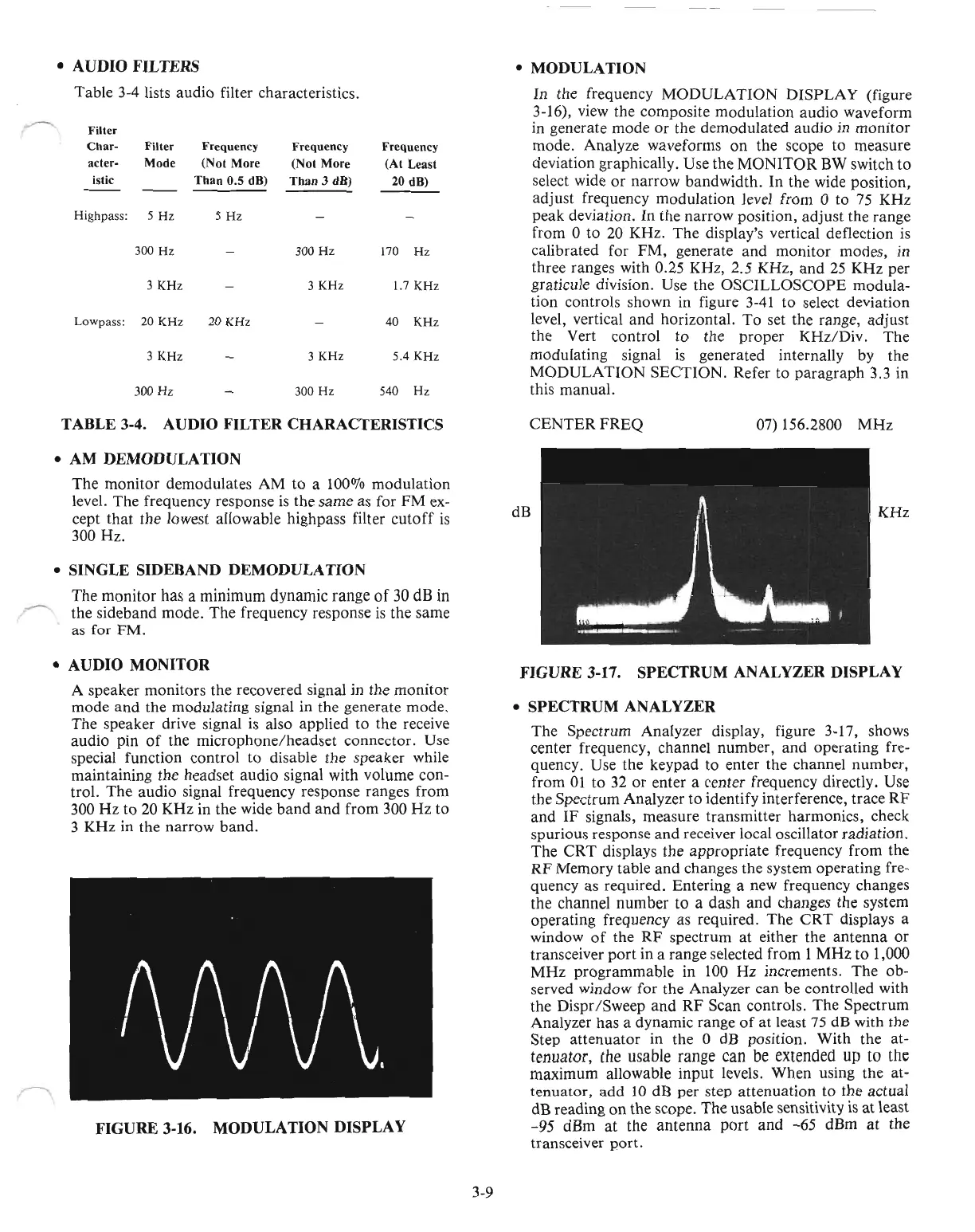
CENTERFREQ
07) 156.2800
MHz
•
AM
DEMODULATION
The
monitor
demodulates
AM
to
a
100070
modulation
level.
The
frequency response is the
same
as for
FM
ex-
cept
that
the
lowest allowable highpass filter
cutoff
is
300
Hz
.
•
SINGLE
SIDEBAND
DEMODULATION
The
monitor
has a
minimum
dynamic
range
of
30
dB in
the
sideband
mode.
The
frequency response
is
the
same
as for
FM.
dB
KHz
•
AUDIO
MONITOR
A speaker
monitors
the
recovered signal in
the
monitor
mode
and
the
modulating
signal in the generate
mode.
The
speaker drive signal
is
also applied
to
the receive
audio
pin
of
the
microphone/headset
connector.
Use
special function
control
to
disable the speaker while
maintaining the headset
audio
signal with volume con-
trol.
The
audio
signal frequency response ranges
from
300
Hz
to
20
KHz
in the wide
band
and
from 300
Hz
to
3
KHz
in the
narrow
band.
FIGURE
3-16.
MODULATION
DISPLAY
3-9
FIGURE
3-17.
SPECTRUM
ANALYZER
DISPLAY
•
SPECTRUM
ANALYZER
The
Spectrum Analyzer display, figure 3-17, shows
center frequency, channel
number,
and
operating
fre-
quency. Use
the
keypad
to
enter
the
channel
number,
from
01
to
32
or
enter a center frequency directly. Use
the
Spectrum
Analyzer
to
identify interference, trace
RF
and
IF
signals, measure
transmitter
harmonics, check
spurious response
and
receiver local oscillator
radiation.
The
CRT
displays
the
appropriate
frequency
from
the
RF
Memory
table
and
changes the system
operating
fre-
quency as required. Entering a new frequency changes
the channel
number
to
a dash
and
changes the system
operating
frequency as required.
The
CRT
displays a
window
of
the
RF
spectrum
at
either
the
antenna
or
transceiver
port
in a range selected
from
1
MHz
to
1,000
MHz
programmable
in 100
Hz
increments.
The
ob-
served window for
the
Analyzer
can
be controlled with
the
Dispr/Sweep
and
RF
Scan controls.
The
Spectrum
Analyzer has a dynamic range
of
at
least
75
dB with the
Step
attenuator
in the 0 dB position.
With
the at-
tenuator,
the usable range
can
be
extended
up
to
the
maximum
allowable
input
levels.
When
using the at-
tenuator,
add
10 dB
per
step
attenuation
to
the actual
dB reading
on
the
scope.
The
usable sensitivity
is
at
least
-95
dBm
at
the
antenna
port
and
-65
dBm
at
the
transceiver
port.

 Loading...

