SECTION 2
DESCRIPTION
MODULATION
Mod
Out
ll<Hz
LCIlt;1
Oll
Mm
Code
SYnlh
lvl
MomlOI
FM
CW
•
AM
•
sse
OSB$C
•
S'NP
'·IQMH7
o
SWP.Ol·lMt-h.
FUNCTION
BFO
Scop~
oc
E~t
\"hmtTlewr
"
Scop
p
AC
DVM
Olsr
Squelch
VoluMe
s.g
L'I'
WIde
•
DotlruodOl,lt
11I1"9~
Opl.
8W
011
DISPLAV
• Gcn
MonMh
•
Modl,I.llfo"
Spt;l(;t
An.ttVltlf
OUpl~)
Gen
•
MemOtt
SI,ll,IIl!l9
eQ
•
Fr£l'(J
Gaumer
low
Narrow
-
.......
,_-MONITOR
----..
__
--
Dc
011
On
Hom
eltl!10
••
l
•
ltlll!!"!III)
fo(v-
POWER
.BElIl
lIaElEI
m.IIEI
Vert
~~~~--,--:;:::----:~-
OSCILLOSCOPE
-
"HI
e.,
v
mSec
(
0""
§O~~
(:o,e."",
t~:
'
J 5 I - +
E"
.15
I
o /
/c.,
Aulo
Norm;ll
/C
PaS'llon
dB
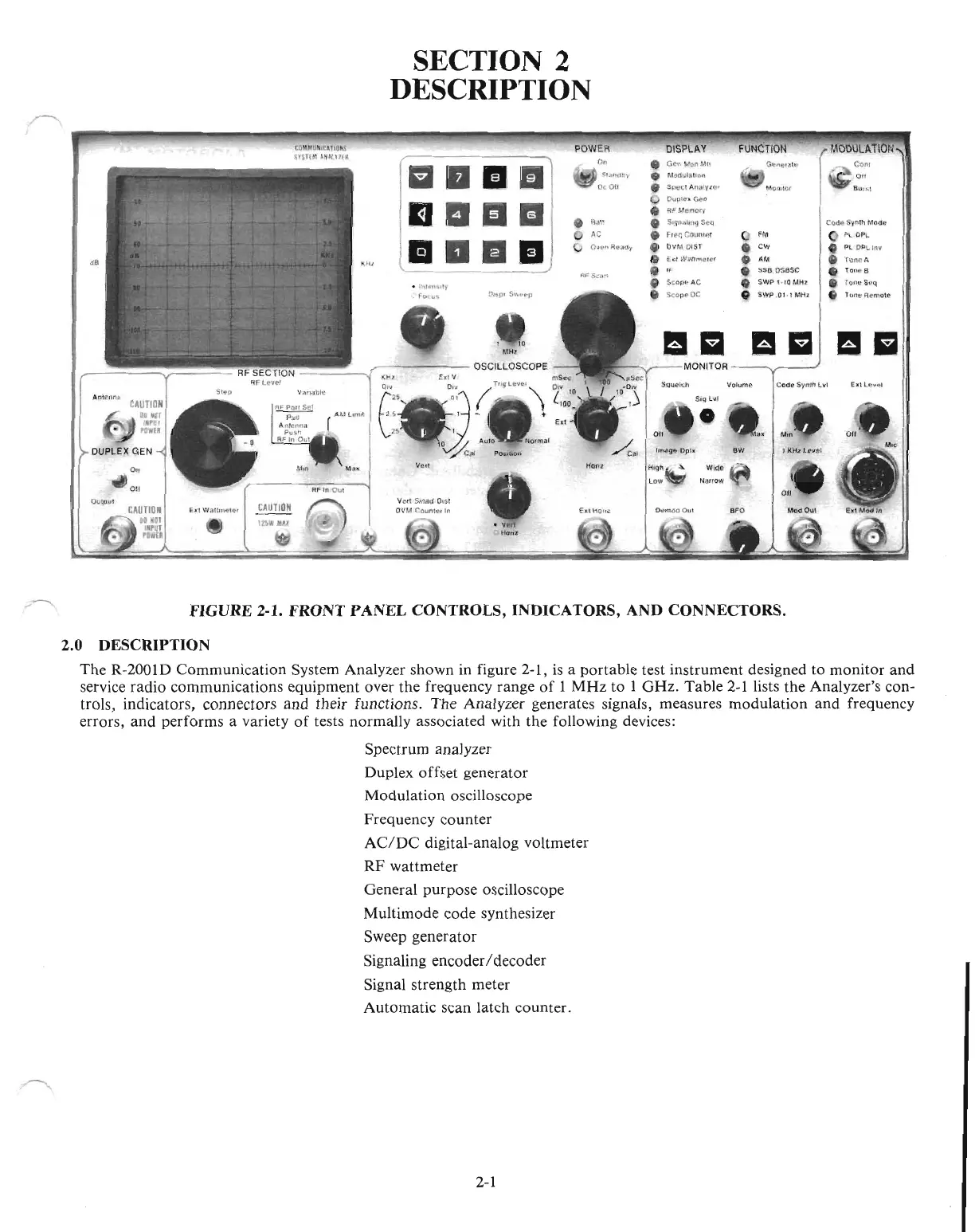
FIGURE 2-1. FRONT
PANEL
CONTROLS, INDICATORS, AND CONNECTORS.
2.0 DESCRIPTION
The
R-2001D Communication System Analyzer shown in figure 2-1,
is
a portable test instrument designed
to
monitor
and
service radio communications equipment over the frequency range
of
I
MHz
to 1
GHz.
Table
2-1
lists the Analyzer's con-
trols, indicators, connectors
and
their functions.
The
Analyzer generates signals, measures modulation
and
frequency
errors,
and
performs a variety
of
tests normally associated with the following devices:
Spectrum analyzer
Duplex offset generator
Modulation oscilloscope
Frequency counter
AC/DC
digital-analog voltmeter
RF
wattmeter
General purpose oscilloscope
Multimode code synthesizer
Sweep generator
Signaling encoderI decoder
Signal strength meter
Automatic scan latch counter.
2-1

 Loading...

