On
011
Oulput
DUPLEX GEN
The
MONITOR
Image/Duplex
switch
controls
th
positive
or
negative signal
of
the offset. As
the
offset
changes, the generate frequency changes
to
reflect
the
new offseL
On
line
I,
enter
the channel
number
to
select
a frequency from the
RF
memory
table. In
DUPLEX
GEN
mode,
the
Image/Duplex
two-position toggle
switch
controls
the
duplex frequency
output
for
above
(High)
or
below (Low) the receive
programmed
frequen-
cy. In
monitor
mode,
this switch selects
the
frequency
of
the local oscillator injection
above
or
below the
pro-
grammed
monitor
frequency
to
remove image in-
terference.
Enter
either the
PL
or
DPL
code
of
the
duplex generate frequency.
If
an
entry
is
made
into
the
PL
location, the
DPL
display changes
to
a
dash.
If
an
entry
is
made
into the
DPL
location,
the
PL
display
changes
to
a
dash.
Line I I indicates the
position
of
the
FUNCTION
switch.
Generate
or
Monitor
mode
deter-
mines the
source
of
modulation
available for system
analysis.
It
is
either applied
to
the duplex
generator
or
recovered
from
the
monitor
receiver. Both positive
and
negative readings
autorange
in
three
digits with full
scale
from
10KHz
to
100 KHz.
The
bargraph
represents
modulation
levels
and
provides a
smooth
nonranging
analog
display
on
a full scale
of
20
KHz
FM.
also changes
to
maintain
the
displayed offset value
whenever a new
monitor
frequency
is
entered.
The
pro-
grammable
duplex
offset
equals the generate frequency
+ / - the
monitor
frequency.
+ 100
ATTEN)
0
+2.06
+45.00
MHz
074.7750
MHz
DPL)
137
06)
029.7750
MHz
CAUTION
10.0'
l.rUI
'0
L:.
Antenna
o
DUPLEX
GEN
DEV
KHz
DPLX
Monitor
DPLX
Offset
DPLX
Generate
PL)
- - -
-2.06
-100
ANT
FIGURE 3-19.· DUPLEX GENERATOR
DISPLAY
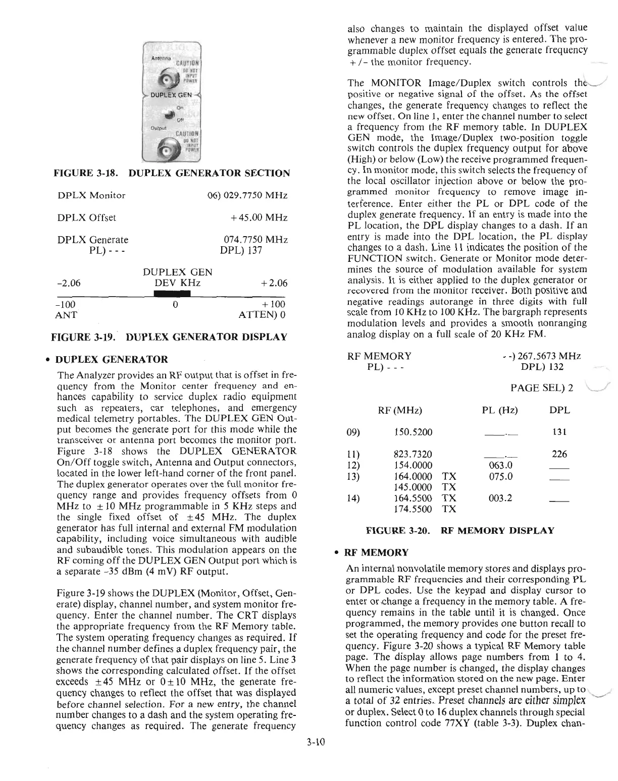
FIGURE
3-18.
DUPLEX
GENERATOR
SECTION
CAUTION
80.01
"PUT
'OWl'
FIGURE
3-20. RF MEMORY
DISPLAY
RF(MHz)
PL
(Hz)
DPL
09) 150.5200
-'-
131
11)
823.7320
-'-
226
12)
154.0000
063.0
13)
164.0000
TX
075.0
145.0000
TX
14)
164.5500
TX
003.2
174.5500
TX
•
RF
MEMORY
An
internal
nonvolatile
memory
stores
and
displays
pro-
grammable
RF
frequencies
and
their
corresponding
PL
or
DPL
codes. Use
the
keypad
and
display
cursor
to
enter
or
,change a frequency in the
memory
table. A fre-
quency
remains in
the
table
until it
is
changed.
Once
programmed,
the
memory
provides
one
button
recall
to
set
the
operating
frequency
and
code
for
the preset fre-
quency. Figure 3-20 shows a typical
RF
Memory
table
page.
The
display allows
page
numbers
from
1
to
4.
When
the
page
number
is
changed,
the display changes
to
reflect
the
information
stored
on
the
new page.
Enter
all
numeric
values, except
preset
channel
numbers,
up
to
a total
of
32 entries
..
Preset
channels
are
either
simplex
or
duplex. Select 0
to
16
duplex channels
through
special
function
control
code 77XY (table 3-3). Duplex
chan-
•
DUPLEX
GENERATOR
The
Analyzer provides
an
RF
output
that
is
offset
in fre-
quency
from
the
Monitor
center frequency
and
en-
hances capability to service duplex
radio
equipment
such
as repeaters,
car
telephones,
and
emergency
medical telemetry portables.
The
DUPLEX
GEN
Out-
put
becomes the
generate
port
for
this
mode
while the
transceiver
or
antenna
port
becomes the
monitor
port.
Figure 3-18 shows
the
DUPLEX
GENERATOR
On/Off
toggle switch,
Antenna
and
Output
connectors,
located in the lower
left-hand
corner
of
the
front
panel.
The
duplex
generator
operates
over the full
monitor
fre-
quency
range
and
provides frequency offsets from 0
MHz
to
±
10
MHz
programmable
in 5
KHz
steps
and
the single fixed
offset
of
±
45
MHz.
The
duplex
generator
has full
internal
and
external
FM
modulation
capability, including voice
simultaneous
with audible
and
subaudible
tones.
This
modulation
appears
on
the
RF
coming
off
the
DUPLEX
GEN
Output
port
which
is
a
separate
-35
dBm
(4 m
V)
RF
output.
Figure 3-19 shows
the
DUPLEX
(Monitor,
Offset,
Gen-
erate) display, channel
number,
and
system
monitor
fre-
quency.
Enter
the
channel
number.
The
CRT
displays
the
appropriate
frequency
from
the
RF
Memory
table.
The
system
operating
frequency changes as required.
If
the channel
number
defines a
duplex
frequency
pair,
the
generate
frequency
of
that
pair
displays
on
line 5. Line 3
shows the
corresponding
calculated offset.
If
the
offset
exceeds ± 45
MHz
or
0 ±
10
MHz,
the
generate fre-
quency
changes
to
reflect the
offset
that
was displayed
before
channel selection.
For
a new entry, the channel
number
changes
to
a
dash
and
the
system
operating
fre-
quency
changes as
required.
The
generate frequency
RF
MEMORY
PL)
- - -
-
-)
267.5673
MHz
DPL)
132
PAGE
SEL) 2
"----./
3-10

 Loading...

