SECTION 3
OPERATION
• SELF-TEST DISPLAY EXAMPLES:
3.0
OPERATION
• GENERAL
The Communications System Analyzer
is
easy to use.
Connectors, controls, and indicators are conveniently
and logically arranged in functional groups outlined in
red
on
the front panel.
The
Analyzer incorporates many
useful applications
that
are not evident
by
examining
the front panel.
The
appropriate section
of
this manual
clearly explains these applications and how to access
them by manipulating the keypad.
The
CRT
displays
an
organized presentation
of
measurement results. A non-
volatile memory conveniently stores the
data
entered
into the system by the operator.
The
system provides
warning messages and audible alarms to ease operation
and minimize errors.
3.1
POWER
SECTION
REFER
TO
ADDENDUM
AT
THE
END
OF
THIS
SECTION
PAGE
3-21
• STANDBY
In Standby
or
center position, if the line cord
is
con-
nected to AC power, the battery charger continues to
operate and power
is
applied to the internal frequency
standard.
On
Slnnnhy
OcOfl
•
DC
OFF
In the full-down position DC
Off,
if the line cord
is
con-
nected to
AC
power, only the battery charging circuit
operates.
B.ll1
AC
FIGURE
3-1.
POWER
CONTROLS
•
POWER
The Analyzer operates on
AC
or
DC. AC can
be
either
100
to
130
VAC
or
200
to
260 VAC,
47
Hz to 400 Hz
capable
of
115 Watts. Use the recessed LINE switch on
the rear panel to select either
110
or
220 voltage. DC
input from
Motorola
battery pack RTP-1002A
or
any
convenient external battery source operates from
+
11
V
to +
16
V, 6.5 amps maximum, with not more than 90
Watts
DC
input. Refer to Section I
of
this manual for
installation instructions for the Motorola battery pack
that
attaches to the rear panel and provides approx-
imately
50 minutes continuous operation. Figure
3-1
shows a three-position toggle switch located to the right
of
the keypad on the front panel and used to control the
Analyzer's power supply.
• ON
The
On,
or
full-up, posItIOn
of
the toggle switch
energizes all circuitry except the battery charger.
• SELF-TEST
When the power switch
is
first turned on, the Analyzer
performs an internal check
of
its own circuits to detect
possible trouble.
If
the system detects an error, during
the course
of
this self-test, a message displays on the
screen to indicate the nature
of
the trouble and provide
some guidance for troubleshooting
and/or
continued
operation.
3-1
• LED INDICATORS
AC LED indicator illuminates whenever AC power
is
connected to the three-pin power connector on the rear
panel. Batt (battery) LED indicator illuminates when-
ever
DC
power
is
connected to the DC
POWER
con-
nector on the rear panel. AC and DC indicators never
illuminate together. The system switches automatically
between AC and DC, with preference for
AC
if
both are
present. Oven Ready LED indicator illuminates auto-
matically when the internal frequency standard has
stabilized and the system
is
ready to operate accurately.
allmll
,
IIIIElEI
11111111
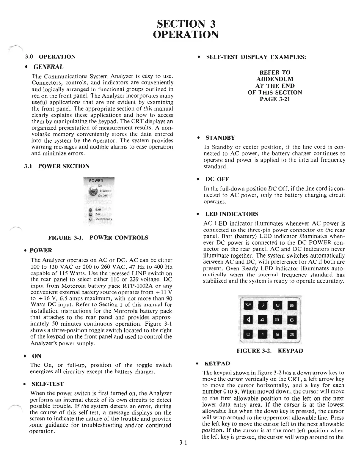
FIGURE
3-2. KEYPAD
• KEYPAD
The
keypad shown in figure 3-2 has a down arrow key to
move the cursor vertically on the
CRT,
a left
arrow
key
to move the cursor horizontally,
and
a key for each
number 0
[0
9.
Wllt:1l moved down, the cursor will move
to the first allowable position to the left
on
the next
lower
data
entry area.
If
the cursor
is
at the lowest
allowable line when the down key
is
pressed, the cursor
will wrap
around
to the uppermost allowable line. Press
the left key to move the cursor left to the next allowable
position.
If
the cursor
is
at the most left position when
the left key
is
pressed, the cursor will wrap
around
to the

 Loading...

