AUDIO FREQUENCY RESPONSE
1.
As shown in figure 4-10, connect the Analyzer's RF
In/Out
port
to
the transmitter's RF output and the
VertiSinad/
Dist input jack
to
the Mod Out jack through a BNC tee fitting connected to the transmitter's microphone audio input.
Disable
PL
and
DPL.
2.
Select DVM/Dist DISPLAY and set it to mode
1,
AC DVM. Set FUNCTION to Monitor FM, attenuator to -40 dB,
MODULATION to Cont and Tone A. Use the keypad to enter the transmitter frequency. Turn
off
the 1 KHz and Ext
Mod controls.
3.
Set DISPLAY to Signaling Sequence. Use the keypad to enter mode
1,
AlB
encode, Tone A and enter the frequency
to be tested.
4. Set DISPLAY to
Gen/Mon
Mtr, key the transmitter, and adjust Code Synth Level control to provide
300/0
of
rated
transmitter deviation.
5. Change DISPLAY
to
DVM/Dist. Note both the transmitter MIC Audio input level in dBm and the test frequency, for
later use.
6. Repeat the above procedure, adjusting Code Synth Level to maintain 30%
of
rated deviation, for each frequency to
be tested.
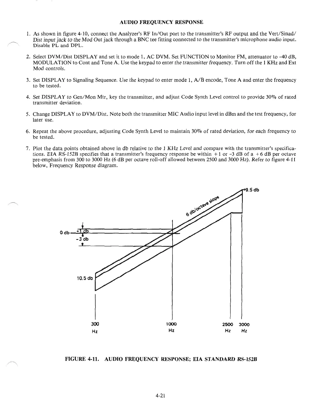
7.
Plot the
data
points obtained above in db relative to the 1 KHz Level and compare with the transmitter's specifica-
tions. EIA RS-152B specifies that a transmitter's frequency response be within
+ 1 or -3 dB
of
a +6 dB per octave
pre-emphasis from 300 to 3000 Hz (6 dB per octave roll-off allowed between 2500 and 3000 Hz). Refer to figure
4-11
below, Frequency Response diagram.
o
db-';"+¥~-----------.,..r;;.'-
-3
db
10.5 db
.5db
300
Hz
1000
Hz
2500
3000
Hz
Hz
FIGURE 4-11. AUDIO FREQUENCY RESPONSE;
EIA
STANDARD RS-152B
4-21

 Loading...

