•
AUTO
TUN"~
MODE
Enable
full-band scan lock with special function control
code
#3300 (table 3-3).
The
monitor
scans its specified
frequency range to automatically acquire and tune
a
strong
input
signal
within
fjve
seconds.
For
faster
ac-
quisition, use special function control code #33XY to
limit the scan range to
100
MHz
increments.
The
minimum
input
signal level for
automatic
frequency ac-
quisition
is
-30
dBm at the
antenna
port
and
0 dBM
at
the transceiver port.
The
word
SCANNING
replaces the
programmed
frequency display. Line 8 displays the ac-
tual input frequency
± I KHz as shown in the example
in figure 3-10. When tuned, dashes replace the
SCANN-
ING
display
and
a dash in the cursor replaces the chan-
nel number. When the
input
signal
is
removed, scanning
resumes.
•
SCAN
LATCH
MODE
Select this variation
of
the
auto
tune mode, using special
function control code #3400
or
34XY
to
program
and
latch
an
auto
tune
frequency. In this mode, the
input
signal is acquired
and
tuned in the same
manner
as for
auto
tune. However, the
programmed
frequency display
shows the word:
•
LATCHED
and
a dash under the cursor instead
of
the preset
number.
The
second line
on
the metering display reads
•
PRESS
0
TO
RESCAN
If
the input signal is removed, the system remains pro-
grammed
to
the last frequency tuned. When the
operator
activates the 0 key, scanning resumes
and
the
word
SCANNING
replaces the word
LATCHED
on
the
display.
The
preset
number
0
appears
under
the cursor.
Also, the
CRT
omits the second line
on
the display as
scanning resumes.
The
scan latch
mode
is
useful
for
locating the transmit
frequency
of
trunked
radios.
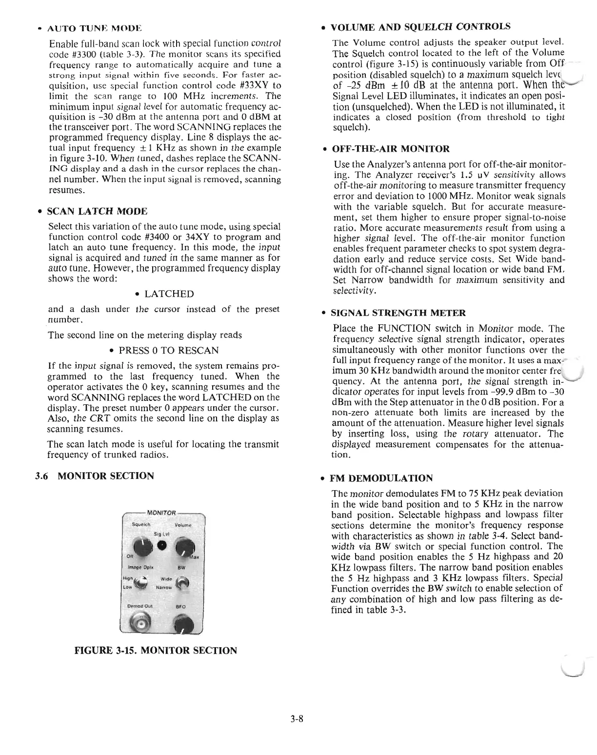
3.6
MONITOR
SECTION
MONITOR
SquelCh
Volume
~19l
...
,
•
0"
....
'PM"
Image
Opht
OW
HI9h~.
Wide
LOIN
w
N;wow
Delima
OuI
BFO
FIGURE
3-15.
MONITOR
SECTION
3-8
•
VOLUME
AND
SQUELCH
CONTROLS
The
Volume
control
adjusts the speaker
output
level.
The
Squelch control located
to
the left
of
the Volume
control
(figure 3-15)
is
continuously variable
from
Off
position (disabled squelch) to a maximum squelch lev(
of
-25
dRm ±
10
dB
at
the
antenna
port.
When
the
Signal Level
LED
illuminates, it indicates
an
open posi-
tion
(unsquelched).
When
the
LED
is
not
illuminated, it
indicates a closed position
(from
threshold to tight
squelch).
•
OFF-THE-AIR
MONITOR
Use the Analyzer's
antenna
port
for off-the-air
monitor-
ing. The Analyzer receiver's 1.5 uV sensitivity allows
off-the-air monitoring
to
measure transmitter frequency
error
and
deviation
to
1000
MHz.
Monitor
weak signals
with the variable squelch. But for accurate measure-
ment, set them higher to ensure
proper
signal-to-noise
ratio. More accurate measurements result from using a
higher signal level.
The
off-the-air
monitor
function
enables frequent
parameter
checks
to
spot
system degra-
dation
early
and
reduce service costs. Set Wide
band-
width for off-channel signal location
or
wide
band
FM.
Set Narrow bandwidth for
maximum
sensitivity
and
selectivity.
•
SIGNAL
STRENGTH
METER
Place the
FUNCTION
switch in
Monitor
mode.
The
frequency selective signal strength indicator, operates
simultaneously with
other
monitor
functions over the
full
input
frequency range
of
the
monitor.
It
uses a max-
imum 30 KHz bandwidth
around
the
monitor
center fre
quency.
At
the
antenna
port,
the signal strength in-
dicator operates for
input
levels from
-99.9
dBm
to
-30
dBm with the Step
attenuator
in the 0 dB position.
For
a
non-zero
attenuate
both
limits
are
increased by the
amount
of
the
attenuation.
Measure higher level signals
by inserting loss, using the
rotary
attenuator.
The
displayed measurement compensates for the attenua-
tion.
•
FM
DEMODULATION
The
monitor
demodulates
FM
to
75
KHz
peak deviation
in the wide
band
position
and
to 5 KHz in the
narrow
band
position. Selectable highpass
and
lowpass filter
sections determine the monitor's frequency response
with characteristics as shown in table 3-4. Select
band-
width via BW switch
or
special function control.
The
wide
band
position enables the 5
Hz
highpass
and
20
KHz
lowpass filters.
The
narrow
band
position enables
the 5
Hz
highpass
and
3
KHz
lowpass filters. Special
Function overrides the BW switch to enable selection
of
any combination
of
high
and
low pass filtering as de-
fined in table 3-3.

 Loading...

