DIS
pI Sweep
3.7
OSCILLOSCOPE
SECTION
sitivity varies continuously over the mlmmum range
from 0.1 volt per division to
10
volts per division. Ad-
just sensitivity with the Vert switch and control.
The time base
is
calibrated with the vernier control fully
clockwise. Normal operation does not include a char- '-.--/
acter display in either Scope AC
or
Scope DC mode.
However, if the operator also selects a SWEEP FUNC-
TION, then the first character line on the CRT identifies
the operating center frequency. The synchronized scope
displays the swept response symmetrically about the
selected carrier center frequency. When Scope AC or
Scope DC DISPLAY
is
selected in conjunction with
sweep function, the oscilloscope horizontal input
is
coupled to the sweep signal. When the scope trace
is
at
the center
of
the screen
(±
1 minor division) the instan-
taneous RF output frequency will be equal
to
the pro-
grammed frequency.
NOTE
liOtll
Ell.IHonl
Position
Veri
I~O
M~'
r
OSCILLOSCOPE
KHz
In all cases the bargraph aids the autoranging digital
scale. The bargraph responds in a modified logarithmic
manner that provides a smooth nonranging analog dis-
play. In other words, the analog display
will
change the
same amount for a 1 volt change
at
10
volts as for a
25
volt change at 250 volts.
SPECTRUM ANALYZER USAGE
The indicated
rf
signal level in the spectrum analyzer mode
is
30db less than actual input at the RF
In/Out
port.
When using the spectrum analyzer for measuring harmon-
ics
of
the
rf
carrier, it
is
necessary to limit the level
of
the
rf
carrier to less than -20dbm (RF
In/Out
port) or less than
-50 dbm (Antenna port) with an external attenuator in
order to maintain the correct harmonic relationship to the
rf
carrier.
---./
Analog
Bargraph
Full Scale Range
0·125w
0-15KHz
0-100KHz
0-100070
0-300V
oto 100% (Dist)
-60db to
Odb
(SINAD)
Wattmeter Element
dependent
0-2.5w to l000w
Function
Power Monitor (above 1
w)
Frequency Error
FM Modulation
AM Modulation
DVM (AC
or
DC)
DIST/SINAD
Ext Wattmeter
The horizontal time base generator provides a linear
horizontal sweep from a minimum rate
of
100
ms
per
division to a maximum rate
of
1
us
per division in six
decade ranges selectable with the Horizontal control.
Use the oscillator Trigger Level switch in automatic or
normal position to synchronize the horizontal time base
to the vertical input signal. In automatic mode, the
scope will trigger continuously. In normal mode, the
scope will trigger when the vertical signal exceeds the
level set by the control. The smaller trigger level control
adjusts the level
at
which a positive going signal triggers
the time base. A separate front panel BNC
port
provides
for the External Horizontal input enabled
by
a seventh
position on the time base control switch. The input sen-
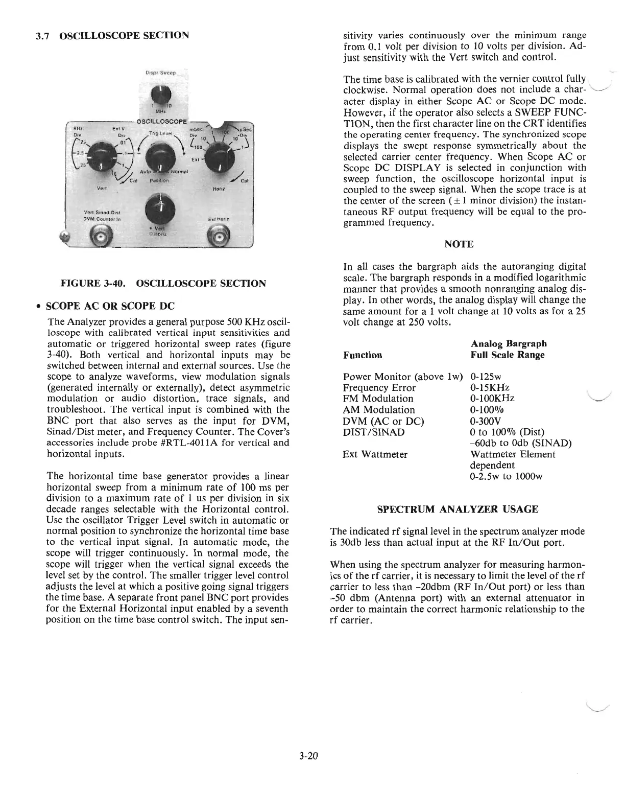
FIGURE
3-40.
OSCILLOSCOPE
SECTION
•
SCOPE
AC
OR
SCOPE
DC
The Analyzer provides a general purpose 500 KHz oscil-
loscope with calibrated vertical input sensitivities and
automatic
or
triggered horizontal sweep rates (figure
3-40). Both vertical and horizontal inputs may be
switched between internal and external sources. Use the
scope to analyze waveforms, view modulation signals
(generated internally or externally), detect asymmetric
modulation or audio distortion, trace signals, and
troubleshoot. The vertical input
is
combined with the
BNC port that also serves as the input for DVM,
Sinad/Dist meter, and Frequency Counter. The Cover's
accessories include probe #RTL-4011A for vertical and
horizontal inputs.
'--/
3-20

 Loading...

