TABLE
3-1.
MODULA
TION/FUNCTION
AVAILABILITY
• The Mod
Out
connector provides external access to the
composite modulation signals. Output impedance
is
600
ohms.
Note: All modulation sources are available at Mod Out
jack while in use as generator modulation. Code Synthe-
sizer Level control simultaneously sets both the
output
level and the modulation level.
Mo
•
, RF
SECTION
'-
the keypad to select any frequency
of
the generator
from
10
KHz to 1,000 MHz in
100
Hz
increments. The
output
range at the antenna
port
and the transceiver
port
provides sufficient amplitude to get through mis-
aligned tuners and receivers.
It
is
especially effective to
change a receiver's frequency. ----./
RF'LP,,;,j
Erl
\V~llmme'
SU;'p
Vanable
FIGURE
3-11.
RF
SECTION
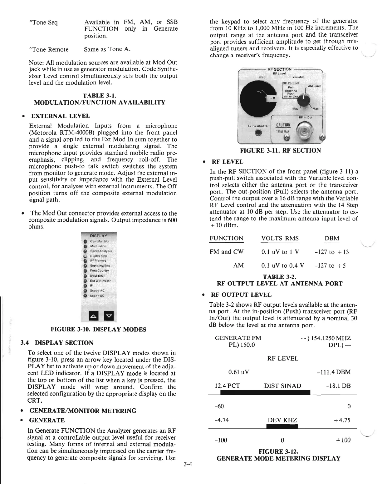
•
RF
LEVEL
In the
RF
SECTION
of
the front panel (figure 3-11) a
push-pull switch associated with the Variable level con-
trol selects either the antenna
port
or
the transceiver
port. The out-position (Pull) selects the antenna port.
Control the
output
over a
16
dB range with the Variable
RF
Level control and the attenuation with the
14
Step
attenuator
at
10
dB per step. Use the attenuator to
ex-
tend the range to the maximum antenna input level
of
+
10
dBm.
Available in FM, AM,
or
SSB
FUNCTION only in Generate
position.
Same as Tone A.
°Tone Seq
°Tone Remote
•
EXTERNAL
LEVEL
External Modulation Inputs from a microphone
(Motorola RTM-4000B) plugged into the front panel
and a signal applied to the Ext Mod In sum together to
provide a single external modulating signal. The
microphone input provides standard mobile radio pre-
emphasis, clipping,
and
frequency roll-off. The
microphone push-to talk switch switches the system
from monitor to generate mode. Adjust the external in-
put sensitivity
or
impedance with the External Level
control, for analyses with external instruments. The
Off
position turns
off
the composite external modulation
signal path.
0.61 uV
-111.4DBM
12.4PCT
DIST SINAD -18.1
DB
-60
0
-4.74 DEV KHZ
+4.75
,-----.
-100 0
+100
FIGURE
3-12.
GENERATE
MODE
METERING
DISPLAY
TABLE
3-2.
RF
OUTPUT
LEVEL AT ANTENNA
PORT
•
RF
OUTPUT
LEVEL
Table 3-2 shows RF
output
levels available at the anten-
na
port.
At
the in-position (Push) transceiver port (RF
In/Out)
the
output
level
is
attenuated by a nominal 30
dB below the level
at
the antenna port.
0.1 uV to 0.4 V
OISPLAV
_
C"n
MooMIr
.•
Modulnhon
e
Speci
A,ni1IVI.t~,
OuplC'k
Ceo
RF
Memory
• Stg"i1lmg
Scq
• F(eq Couniel
• OVM DIST
8 E
..
I
Waltmtl'ler
•
IF
'"
SCOUt'
AC
•
Scope
DC
1111
FIGURE
3-10. DISPLAY MODES
3.4
DlSPLA
Y SECTION
To
select one
of
the twelve DISPLAY modes shown in
figure 3-10, press
an
arrow key located under the DIS-
PLA
Y list to activate up
or
down movement
of
the adja-
cent LED indicator.
If
a DISPLAY mode
is
located at
the top
or
bottom
of
the list when a key
is
pressed, the
DISPLAY mode will wrap around. Confirm the
selected configuration by the appropriate display
on
the
CRT.
•
GENERATE/MONITOR
METERING
•
GENERATE
In
Generate FUNCTION the Analyzer generates
an
RF
signal
at
a controllable
output
level useful for receiver
testing. Many forms
of
internal and external modula-
tion can be simultaneously impressed
on
the carrier fre-
quency
to
generate composite signals for servicing. Use
3-4
FUNCTION
FM and CW
AM
GENERATEFM
PL) 150.0
VOLTS RMS
0.1 uV to 1 V
RF
LEVEL
DBM
-127 to +
13
-127 to
+5
- - ) 154.1250
MHZ
DPL) ---
'-.....-/

 Loading...

