AM MODULATION LINEARITY TEST
1.
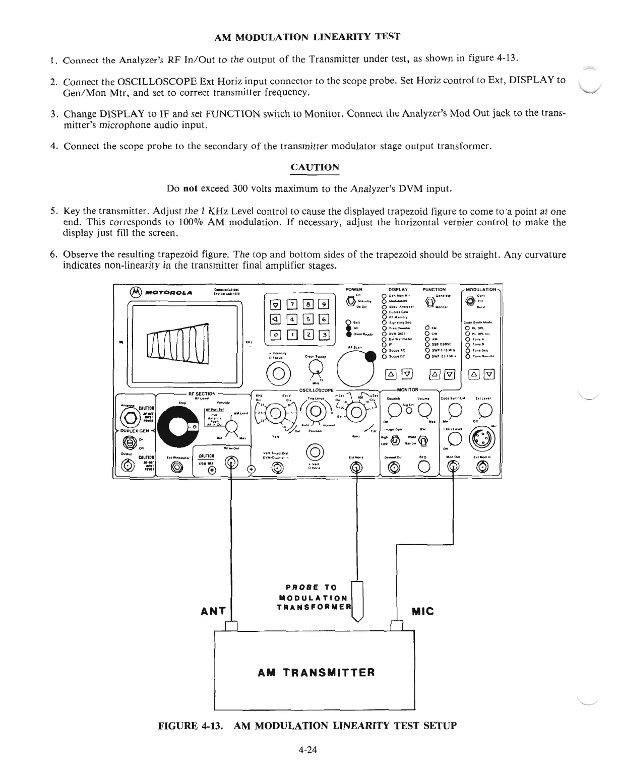
Connect the Analyzer's RF
In/Out
to the
output
of
the Transmitter under test, as shown in figure 4-13.
2. Connect the OSCILLOSCOPE Ext Horiz input connector to the scope probe. Set Horiz control to Ext, DISPLAY to
Gen/Mon
Mtr, and set to correct transmitter frequency.
3. Change
DlSPLA
Y
to
IF and set FUNCTION switch to Monitor. Connect the Analyzer's Mod
Out
jack to the trans-
mitter's microphone audio input.
4.
Connect the scope probe to the secondary
of
the transmitter modulator stage
output
transformer.
CAUTION
Do
not
exceed 300 volts maximum to the Analyzer's DVM input.
5.
Key the transmitter. Adjust the I KHz Level control to cause the displayed trapezoid figure to come tO'a point at one
end. This corresponds to
100070
AM modulation.
If
necessary, adjust the horizontal vernier control to make the
display
just
fill the screen,
6.
Observe the resulting trapezoid figure. The top and bottom sides
of
the trapezoid should be straight. Any curvature
indicates non-linearity in the transmitter final amplifier stages.
'--
~~
MODULATION
o
Pl
OP~
o
PlO~I".
Olo
...
",
0
10
..
'1
Olo
s...q
OlO
"
....
ol.
C.d.S'
..
I1
....
_
@~
0 ••
Oew
°
..
OSSIIOSllSC
OSWP
•. 10MHl
OSWP'Ol.IMHI
FUNCTIONDISPLAYPOWER
@][2]0w
@]000
0800
CO_UllI""01S
Inn.'lLllun
•
®MOTORO&;A
,ft""
o e
.......
"
........
I "
..
~
s,.",,".,
0 "0<1
..
""""
1m
@
011
Dc
011 0
S"~,
"',,.,,
...
,
Y'
"'
....
n.'
......
8
~;:
..
:.~~
i
e.u
OS,,""hn,S.q
AC 0 F
...
qC
....
"'.,
O.onlluCl,
OOVIIIlOtST
Of.,won_,
•.
.l"~n~b
A'k_"
g~~~
_ @
'g'
Oo~~
I AF
II~ECT:ON
11"'
h....
OSCillOSCOPE
",S.u
..,
~~s.~
MONITOR
--V---
J
@
--ClUTlO.·
..• ,
..
:".:::-
["@~~
(,@'o"~
l:':~o"O
,<')
"0"'"
~O'
'0·"-
en"
"0"''''
o
'EI
Q
~~.
~"l_1
(:,
§.
- +
fo!~
Y
o
",
In
0\11
10 "',,10 H
.......
l
OIl
......."
all
DUPLEX GEN
-j'..,
...
',-
~"
,~
...
0".
ow
"".
,....
©5~'
@Oo
-
...
""
_..
."'@ ._@ 0
~
~
...
'
00
CAUTIDI
,,~....
""
_~"
"6'
,..
.."..
""
0
@
CA~1
..
~,
..
-","®
~
$
".©''"
~
© °i' 6
~
'©'
ANT
n
PROBE
TO
MODULATION
TRANSFORMER
n
MIC
AM
TRANSMITTER
'-----"'
FIGURE 4-13. AM MODULATION LINEARITY TEST SETUP
4-24

 Loading...

