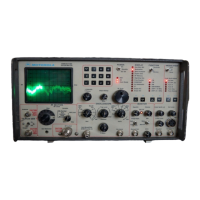
• ACCESSORIES
SUPPLIED
FRONT COVER - The front cover protects the front
panel and its components during transit or while the
Analyzer is not in use.
The
front cover stun:s
the
power
cord, antenna, cables. and other equipment needed for
on-site servicing. PN #15·80335A70.
ANTENNA - The fused BNC connected antenna re-
ceives off-the-air signals.
PN
#TEKA-24A.
BNC to Type N Adapter.
PN
#58-84300A98.
DC POWER CONNECTOR KIT.
PN
#RPX-4097A.
In-Line Wattmeter Adapter.
PN
#RTL-4055B.
MANUAL - The Operator's Manual contains descrip-
tions and instructions for properly using the Analyzer.
PN
#68P81069A66-0.
Oscilloscope
& Meter Probe - A probe
(xl),
with
attachments, provides general servicing needs.
PN
#RTL-4058A.
POWER
CORD - The three-conductor cord powers
the Analyzer by AC and charges the optional battery
pack. Its right-angle design allows the Analyzer to stand
on end. PN
#30-80336A36.
SUN SHADE - Snap the Sun Shade over the CRT
screen to observe displays even in bright sunlight.
PN
#15-80335A55.
TEST MICROPHONE.
PN
#RTM-4000B.
12
VDC POWER CONNECTOR KIT.
PN
#RPX-4097A.
•
OPTIONAL
ACCESSORIES
BATTERY PACK - A
13.6 volt battery attaches di-
rectly to the back
of
the Analyzer to provide
50
minutes
of
continuous operation. Built-in circuitry charges the
battery when the power switch
is
in
Off
or Standby posi-
tion.
If
battery power falls below
11
volts, a warning ap-
pears on the CRT. The battery can be installed in the
field
but
it cannot be used in conjunction with IEEE-448
Interface Bus or Blower.
PN
#RTP-1002A.
DELUXE TELESCOPING ANTENNA.
PN
#RTA-
4000A.
600
OHM
LINE
MATCHING
TRANSFORMER
Use for
600
ohm balanced lines.
PN
#RTL-1003A.
PROTECTIVE CANVAS COVER - A rugged, padded
fabric cover protects the Analyzer from excessive field
wear.
PN
#RTL-4056B.
RF DETECTOR PROBE.
PN
#RTL-4075A.
1
TRANSIT CASE.
PN
#RTL-4065A.
1-4
• MODEL OPTIONS
• Cellular Test Functions - Model R-2008D provides
capability in one test instrument for servicing traditional
PM
eommunje~tjons
~nd.
with
the
cellular option, the
new cellular radio systems:
•
CELL-TO-MOBILE
SIGNALING
ACCEP-
TANCE TESTS
• MOBILE-TO
CELL
SIGNALING
ACCEP-
TANCE TESTS
• AUTOMATIC RF TESTS
• MANUALLY SELECTED RF TESTS.
• High Stability (HS) Oscillator - Use this oscillator
to improve stability over the standard TCXO time
base to
+/-5 X 10-
8
maximum error, over the
temperature range
of
0 to 55°C. A front panel LED
(Oven Ready) indicates when the ovenized crystal has
stabilized.
MODELS (See Specifications)
R-200ID Basic Model
R-200ID/HS
R-200lD/HSI220
R-2002D/HS
R-2002D/HSI220
R-2008D/HS
R-2008D/HSI220
R-2009D/HS
R-2009D/HSI220
• IEEE-488 STANDARD INTERFACE BUS
This option enables using the Analyzer
as
a program-
mable measurement instrument. For example, An-
alyzer Model R-2002D when combined with the suit-
able programmable controller and applications soft-
ware becomes the heart
of
an automated RF test sys-
tem. Control or monitor all
of
the Analyzer's func-
tions via the IEEE Bus. Perform full sequential test
routines, quickly and repetitively, with little operator
interaction.
• MODULE SERVICE KIT
The Extender Board Kit aids servicing the Analyzer's
modules with printed circuit board edges. Use with
A2, A3, A4, A5, A6, A
7,
A9, and A12 modules.
PN
#RPX-4379A.

 Loading...