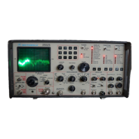
OPERATOR'S MANUAL
COMMUNICATIONS SYSTEM ANALYZER R-200ID
TABLE
OF
CONTENTS
Page
Page
Limited Warranty
ii
RF Sweep Generator
3-5
Safe Handling
v
Monitor Mode
3-5
Specifications
VII Special Function Mode
3-6
Table
of
Contents
ix
Special Function Control Codes
3-7
List
of
lllustrations
XI
Auto
Tune
Mode
3-8
List
of
Tables
xii
Scan Latch Mode
3-8
List
of
Abbreviations
XIII
Monitor Section
3-8
Volume And Squelch Controls
3-8
Section 1
- Introduction
Off-The-Air Monitor
3-8
Signal Strength Meter
3-8
Scope
of
Manual
I-I FM Demodulation
3-8
Service
I-I Audio Filters
3-9
Test Equipment Service Centers
1-1
AM Demodulation
3-9
Replacement Parts Orders
1-2
Single Sideband Demodulation
3-9
Area
Parts
Offices
1-2
Audio Monitor
3-9
Installation
1-3
Modulation
3-9
Packing
1-3
Spectrum Analyzer
3-9
Initial Set-up
1-3
Duplex Generator
3-10
Battery Pack
1-3
RF Memory
3-10
Trace Rotation Adjustment
1-3
Entry With Memory Table
3-11
Accessories
1-4
Entry Without Memory Table
3-11
Preset Turn-On
3-11
Section 2 - Description
Signaling Sequence
3-11
Signaling Sequence Menu
3-11
Description
2-1
Decode Mode Screens
3-11
Front
Panel
2-2
PL
Decode
3-12
Rear Panel
2-10
DPL
Decode
3-13
Bottom Panel
2-10
A/B
Encode
3-13
Two-Tone Sequential Paging
3-13
Section
3 - Operation
5/6
Tone Encode
3-13
Cap
Codes
3-14
General
3-1
5/6
Tone Decode
3-14
Power Section
3-1
Select V Encode
3-14
Self-Test
3-1
Select V Decode
3-15
Keypad
3-1
General Encode
3-15
CRT
Display Screen
3-2 General Decode
3-15
System Warnings
3-2
Mobile Telephone Signaling
3-15
Function Section
3-2
IMTS Mobile Originated
3-
J6
Modulation Section
3-3
IMTS Base Originated
3-16
Fixed
I KHz Tone
3-3
MTS Mobile Telephone
3-16
Code Synthesizer
3-3
2805 Base Originated
3-17
Modulation/Function
3-3
Tone Sequence
3-17
External Level
3-4
Tone Remote (Encode)
3-17
Display Section
3-4
Tone
Remote (Decode)
3-17
Generate/Monitor
Metering
3-4
Frequency Counter
3-18
Generate
3-4
(DVM/DlST)
Digital Voltmeter/Distortion Mode
3-18
RF
Level
3-4
External Wattmeter
3-19
RF
Output
Level
3-4
Intermediate Frequency (IF) Mode
3-19
Generate Mode
3-5
Oscilloscope Seclion
3-20
RF
Scan
Control
3-5
Scope
AC
or
Scope
DC
3-20
Analog Synthesizer Tuning (AST)
3-5
Addendum - Self Test Displays
3-21
ix

 Loading...