Line 1 displays the mode, function,
and
current oper-
ating frequency.
•
GENERATE
MODE
Figure 3-12 defines a generate mode metering display.
To
operate, place
FUNCTION
switch in Generate posi-
tion. Press a
FUNCTION
arrow key to select a signal,
--PM for example.
From
the keypad, enter the desired
frequency. The
Gen/Mon
Mtr and FM LED's
il-
luminate
and
the
CRT
displays GENERATE FM
and
the carrier frequency. Use RF Scan control to tune up
or
down. Adjust deviation using the 1 KHz Level control.
The CRT displays a complete summary
of
all
parameters including carrier frequency, selected code,
RF
level in volts and dBm (analog and digital), devia-
tion or percent modulation. The display
is
explained
here line-by-line.
I) GENERATE FM
••) 154.1250
MHZ
2)
PL)
150.0
DPL)
•••
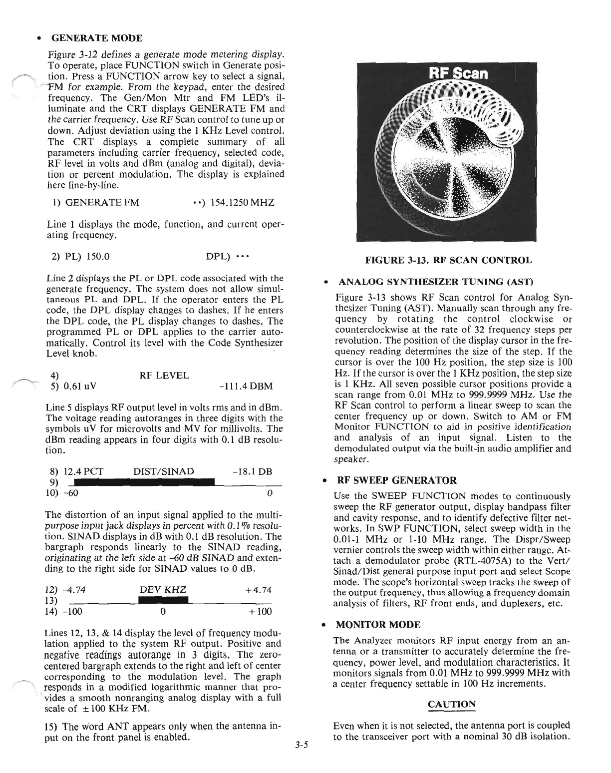
FIGURE
3-13.
RF
SCAN
CONTROL
Line 5 displays RF
output
level in volts rms and in dBm.
The voltage reading autoranges in three digits with the
symbols uV for microvolts
and
MV
for millivolts. The
dBm reading appears
in
four digits with
0.1
dB resolu-
tion.
Line 2 displays the
PL
or
DPL
code associated with the
generate frequency. The system does not allow simul-
taneous
PL
and DPL.
If
the operator enters the
PL
code, the
DPL
display changes to dashes.
If
he enters
the
DPL
code, the
PL
display changes to dashes. The
programmed
PL
or
DPL
applies to the carrier auto-
matically. Control its level with the Code Synthesizer
Level knob. .
4)
5) 0.61
uV
RF
LEVEL
-111.4 DBM
•
ANALOG
SYNTHESIZER
TUNING
(AST)
Figure
3-13
shows
RF
Scan control for Analog Syn-
thesizer Tuning (AST). Manually scan through any fre-
quency by
rotating
the
control
clockwise
or
counterclockwise
at
the rate
of
32 frequency steps per
revolution. The position
of
the display cursor in the fre-
quency reading determines the size
of
the step.
If
the
cursor
is
over the
100
Hz position, the step size
is
100
Hz.
If
the cursor
is
over the 1 KHz position, the step size
is
1 KHz. All seven possible cursor positions provide a
scan range from 0.01 MHz to 999.9999 MHz. Use the
RF Scan control to perform a linear sweep to scan the
center frequency up
or
down. Switch to AM
or
FM
Monitor FUNCTION to aid in positive identification
and analysis
of
an
input signal. Listen to the
demodulated
output
via the built-in audio amplifier and
speaker.
• RF SWEEP GENERATOR
Use the SWEEP FUNCTION modes to continuously
sweep the RF generator
output,
display bandpass filter
and cavity response,
and
to identify defective filter net-
works. In SWP FUNCTION, select sweep width in the
0.01-1 MHz
or
1-10
MHz range. The Dispr/Sweep
vernier controls the sweep width within either range. At-
tach a demodulator probe (RTL-4075A) to the Vert!
Sinad/Dist general purpose input port and select Scope
mode. The scope's horizontal sweep tracks the sweep
of
the
output
frequency, thus allowing a frequency domain
analysis
of
filters, RF front ends, and duplexers, etc.
o
+100
+4.74
-18.1 DB
o
DEV KHZ
DIST/SINAD
8)
12.4
PCT
9)
10)
-60
12)
-4.74
13)
_
14)
-100
The distortion
of
an input signal applied to the multi-
purpose input jack displays in percent with 0.1 % resolu-
tion. SINAD displays in dB with 0.1 dB resolution. The
bargraph responds linearly to the SINAD reading,
originating at the left side at
-60
dB SINAD
and
exten-
ding to the right side for SINAD values
to
0 dB.
Lines 12,
13,
&
14
display the level
of
frequency modu-
lation applied to the system RF output. Positive and
negative readings autorange in 3 digits. The zero-
centered bargraph extends to the right
and
left
of
center
corresponding
to
the modulation level. The graph
responds in a modified logarithmic manner
that
pro-
vides a smooth nonranging analog display with a full
scale
of
± 100 KHz FM.
15)
The w'ord
ANT
appears only when the antenna in-
put on the front panel
is
enabled.
3-5
•
MONITOR
MODE
The Analyzer monitors
RF
input energy from an an-
tenna
or
a transmitter to accurately determine the fre-
quency, power level, and modulation characteristics.
It
monitors signals from 0.01
MHz
to 999.9999 MHz with
a center frequency settable in 100
Hz
increments.
CAUTION
Even when it
is
not selected, the antenna
port
is
coupled
to the transceiver
port
with a nominal 30 dB isolation.

 Loading...

