• EXTERNAL WATTMETER
Figure 3-37 shows a
DC
DVM display
of
the +
or
- in-
put
voltage.
In
the
DC
mode,
the voltage response to
frequencies
above
50
Hz
attenuates at least 20 dB.
Maximum
"N"
Type
"UHF"
Type
Frequency
Power Connector Connector
(MHZ) (Walls)
Model
Model
2-30 250
ST-1296
2-30 2500"
ST-1299
25-60
5
ST-1280B
ST-1281B
25-60
10
ST-1285B
S1-1284B
50-125
5 ST-1283B
ST-1282B
50-125
10
ST-1286B ST-1287B
25-100
25
ST-1204B
ST-1244B
25-100
50 S1-1205B ST-1245B
25-100
100
ST-1206B
ST·1246B
25-100
250 ST-1207B
ST-1247B
25-100
500····
ST-1208B
ST-1248B
100-250
5 ST-1212B
ST-1252B
100-250
10
ST-1213B
ST-1253B
100-250
25
ST-1214B
ST-1254B
100-250
50 ST-1215B ST-1255B
100-250
100 ST-1216B ST-1256B
100-250 250 ST-1217B
ST-1257B
100-250
500····
ST-1218B ST-1258B
200-250
2.5 ST-1221B S1-1261B
200-550
5 ST-1222B
ST-1262B
200-550
10
ST-1223B
ST-1263B
200-550
25
ST-I224B ST-1264B
200-550
50 ST-1225B ST-1265B
200-550
100
ST-1226B ST-1266B
200-550
250
ST-1227B
ST-1267B
200-550
500""
ST-I228B
ST-1268B
500-1000
2.5
ST-I231B'
ST-1271B
500-1000
5 ST-1232B' ST-1272B
500-1000
10
ST-J233B'
ST-1273B
500-1000
25
ST-1234B' ST-1274B
500-1000 50
ST-1235B' ST-1275B
500-1000
100
ST-1236B' ST-1276B
500-1000
250"" ST-1237B' ST-1277B
500-1000
500'"
ST-1238B' ST-1278B
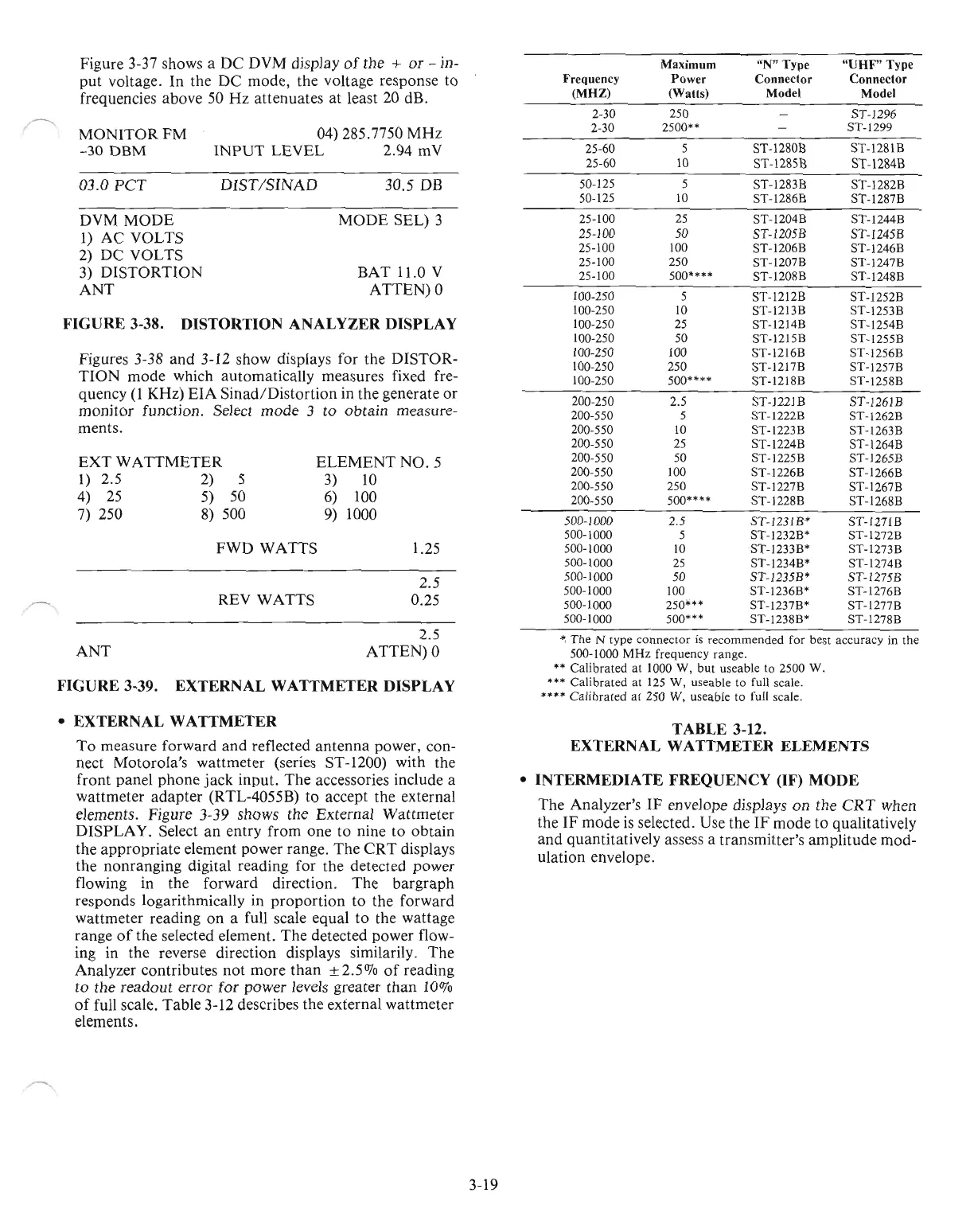
" The N type connector
is
recommended for best accuracy in the
500-1000
MHz
frequency range.
••
Calibraled
at
1000 W, but useable to 2500 W.
...
Calibrated at
125
W, useable to full scale.
••••
Calibrated
at
250 W, useable to full scale.
TABLE 3-12.
EXTERNAL WATTMETER ELEMENTS
• INTERMEDIATE FREQUENCY (IF) MODE
The
Analyzer's
IF
envelope displays
on
the
CRT
when
the
IF
mode
is
selected. Use the
IF
mode
to
qualitatively
and
quantitatively assess a
transmitter's
amplitude
mod-
ulation envelope.
1.25
2.5
0.25
30.5 DB
MODE
SEL)
3
ELEMENT
NO.5
3)
10
6) 100
9)
1000
DIST/SINAD
REV
WATTS
FWD
WATTS
04) 285.7750
MHz
INPUT
LEVEL
2.94 mV
MONITORFM
-30
DBM
DVM
MODE
I)
AC
VOLTS
2)
DC
VOLTS
3)
DISTORTION
ANT
03.0
PCT
EXT
WATTMETER
1)
2.5 2) 5
4)
25
5) 50
7) 250 8) 500
ANT
Figures 3-38
and
3-12 show displays for the
DISTOR-
TION
mode
which
automatically
measures fixed fre-
quency
(l
KHz)
EIA
Sinad/Distortion
in
the
generate
or
monitor
function. Select
mode
3
to
obtain
measure-
ments.
To
measure
forward
and
reflected
antenna
power, con-
nect
Motorola's
wattmeter
(series ST-1200) with the
front
panel
phone
jack
input.
The
accessories include a
wattmeter
adapter
(RTL-4055B)
to
accept the external
elements. Figure 3-39 shows
the
External
Wattmeter
D1SPLA
Y.
Select
an
entry
from
one
to
nine
to
obtain
the
appropriate
element
power
range.
The
CRT
displays
the
nonranging
digital reading for
the
detected power
flowing in the
forward
direction.
The
bargraph
responds logarithmically in
proportion
to
the
forward
wattmeter
reading
on
a full scale
equal
to
the
wattage
range
of
the selected element.
The
detected power flow-
ing in
the
reverse direction displays similarily.
The
Analyzer
contributes
not
more
than
±2.5OJo
of
reading
to
the
readout
error
for
power
levels greater
than
10%
of
full scale.
Table
3-12 describes
the
external
wattmeter
elements.
BAT
11.0 V
ATTEN)0
FIGURE 3-38. DISTORTION ANALYZER DISPLAY
2.5
ATTEN)0
FIGURE 3-39. EXTERNAL WATTMETER DISPLAY
3-19

 Loading...

