MAINTENANCE AND OPERATING MANUAL
Description
HAS T 070÷140
35
ENGLISH
EN
The data in this manual are not binding and they can be modified by the manufacturer without notice. Reproduction of this manual is strictly prohibited.
CHAPTER 3
DESCRIPTION
3.1 Operating principle
The unit is equipped with two separate and independent refrigerant circuits. A plate evaporator allows heat exchange between
the refrigerant and the process fluid.
Suitable compressors are utilised to compress freon in order to achieve a change from the gaseous to the liquid phase. In this
stage the refrigerant gas releases energy in the form of heat.
The liquid refrigerant enters the evaporator where it expands and returns to its initial gaseous state. As it returns to the
gaseous state the refrigerant absorbs energy in the form of heat. In compliance with the first principle of thermodynamics, the
heat is released by the process fluid that flows over the surfaces of the evaporator at a temperature that is higher than that of
the refrigerant fluid.
During winter mode operation the unit serves to heat the process fluid, in which case the cycle is reversed and the evaporator
functions as a condenser.
The following parameters are managed by an electronic control unit:
• evaporator water inlet temperature to keep it within the preset limits;
• the evaporator water outlet temperature and the pressure difference between evaporator inlet and outlet water
to avoid the risk of freezing in low or zero flow conditions.
3.2 Components
Information on the components of standard units is given below.
Non-standard materials
may be utilised in order to meet specific requirements.
In this case refer to the offer data.
All standard units can be equipped with the following components:
• high pressure switches (see chapter "7.2 High pressure switches (HP)");
• high/low pressure transducers;
• check valves;
• 4-way cycle reversal valves;
• liquid receivers (see heading "3.2.6 Liquid receiver");
• relief valves on the high pressure line;
• refrigerant shut-off valves;
• solenoid valve on the liquid line;
• filter-dryers;
• liquid sight-glass;
• thermostatic expansion valves complete with external pressure equalizer;
• water differential pressure switch (not present);
• flow switch.
All welding for connections of components is performed with silver alloy and cold sections of the copper pipes are clad with
insulating material to prevent the formation of condensation.
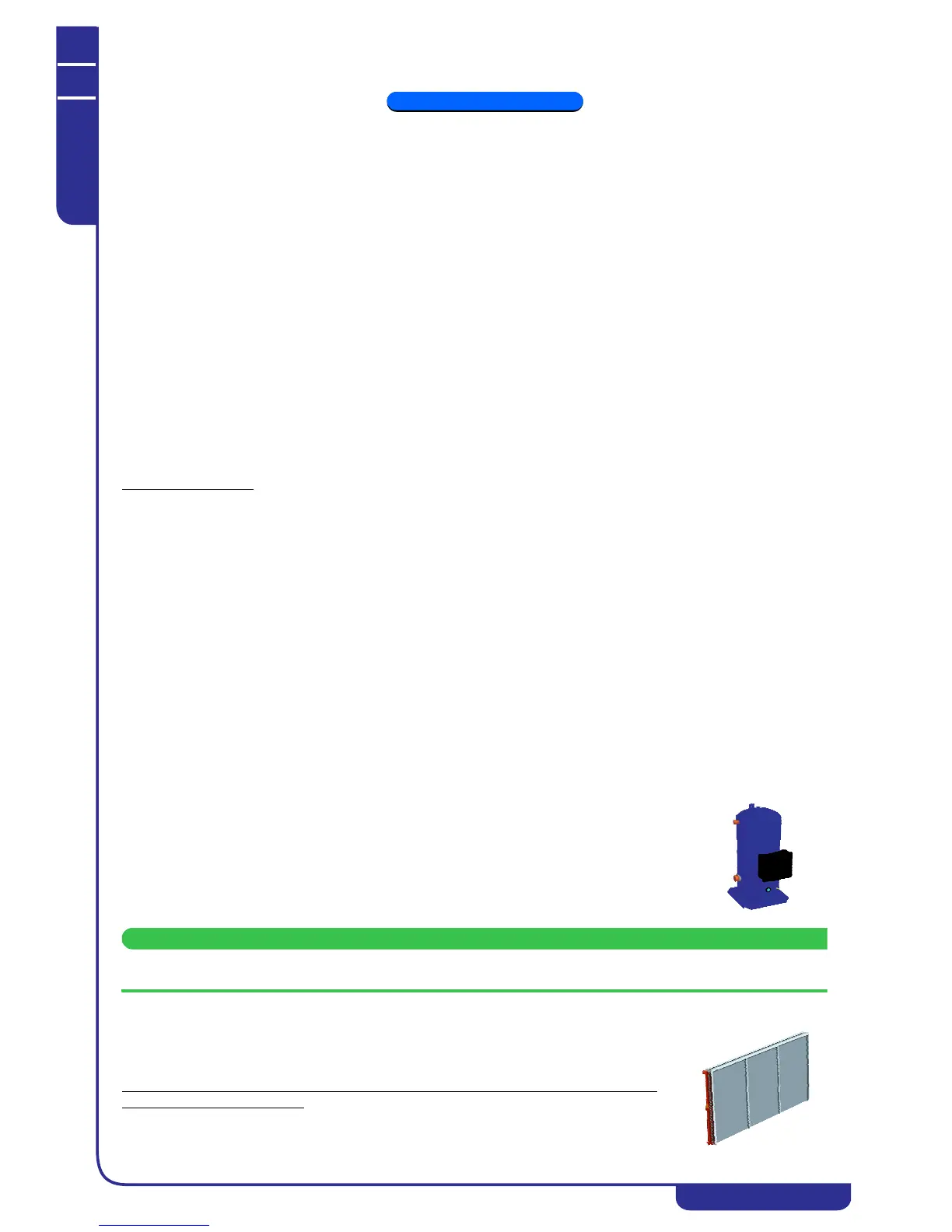
3.2.1 Compressors
The compressors are of the SCROLL type and are quipped with built-in overtemperature protection
in the motor windings, check valve on the discharge line and by-pass between suction and discharge
lines.
Shut-off valves on the suction and discharge lines can be supplied on request.
Each circuit of the units is equipped with an oil equalisation line between the compressors.
The compressors are installed on rubber antivibration mounts and housed in a compartment that is
acoustically insulated by means of sound-absorbing matting in low noise versions (SN and SSN).
It is not necessary to power the crankcase heater in advance before commissioning the unit.
3.2.2 Condensers
The condensers are heat exchangers of the finned core type, cooled by a flow of air supplied by
the fans, and equipped with copper tubes, aluminium fins, and galvanized carbon steel
shoulders. Each refrigerant circuit includes a condensing coil and an associated row of fans.
When the unit changes over from chiller operation to heat pump operation (HEAT PUMP - “WINTER” mode) the condenser can be
considered to be equivalent to an evaporator. To avoid ice formation in the condensate drain pan, hot gas is
extracted from the compressor discharge line and delivered to the relative coil circuit where it
condenses and transfers its heat.