MAINTENANCE AND OPERATING MANUAL
Installation
HAS T 070÷140
40
ENGLISH
EN
The data in this manual are not binding and they can be modified by the manufacturer without notice. Reproduction of this manual is strictly prohibited.
CHAPTER 4
INSTALLATION
4.1 Foreword
This manual is addressed to personnel responsible for installing, using and servicing the unit.
The unit described is designated CHILLER or HEAT PUMP.
The expression “pressure” is used to indicate relative pressure.
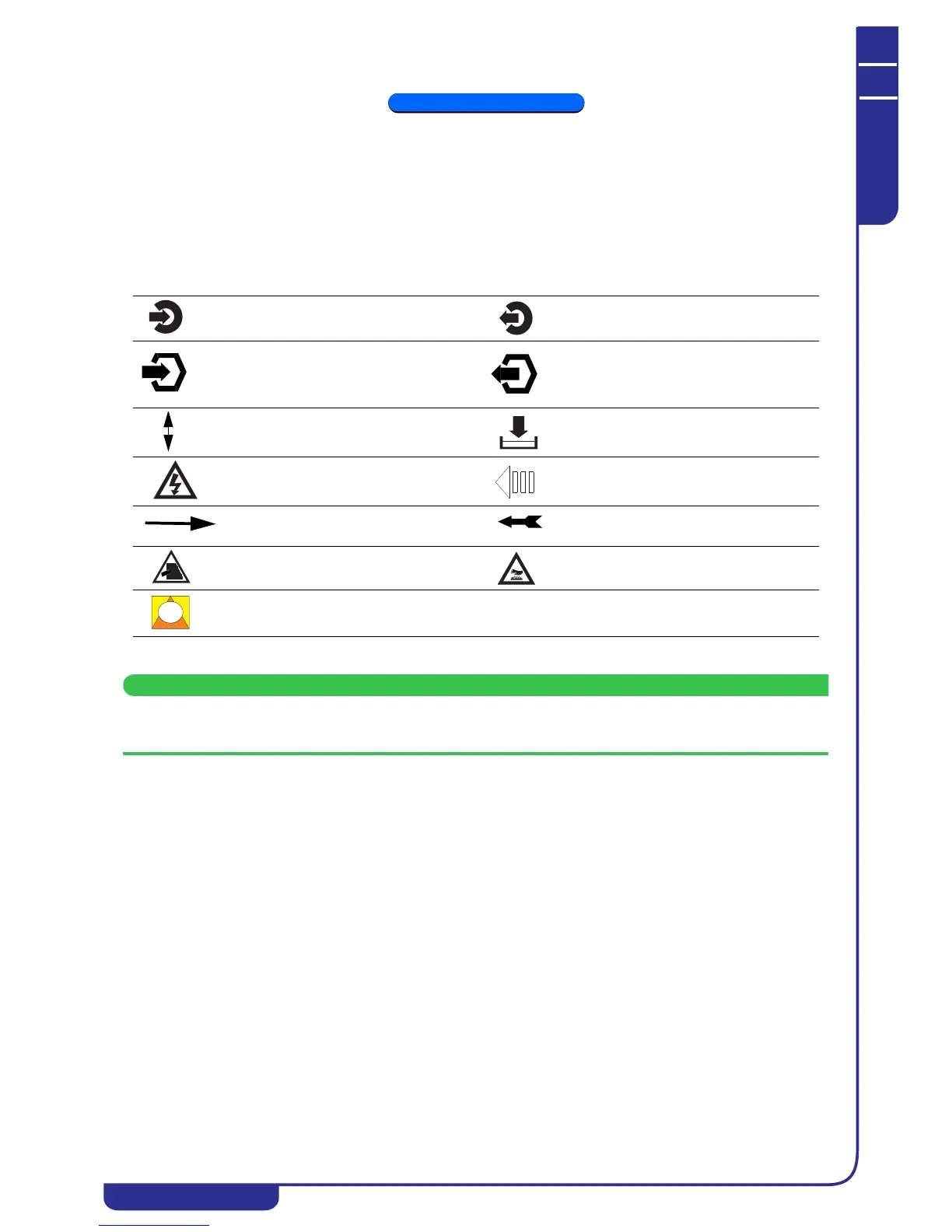
4.2 Symbols
Symbols present on the unit and also in the dimensional drawings and refrigerant circuit diagrams.
4.3 Installation
Before installing or operating these units, read the chapter concerning " Safety". The unit must be installed in
accordance with current national legislation in the country of use.
4.3.1 Inspection
As soon as the unit has been unpacked check it carefully for damage.
4.3.2 Location
1. The unit can be installed either outdoors or in an enclosed environment, depending on the degree of IP protection
of the electrical panel and the unit itself.
2. If the unit is installed indoors the place of installation must be well ventilated. In certain cases it may be necessary
to install ventilation fans or extractor fans in order to reduce room temperature.
3. The ambient air must be clean, avoid sea ambients (brackish air), and not contain flammable gas or corrosive
solvents.
4. The minimum and maximum working ambient temperature are specified on the unit data plate. Ensure that the
unit is not installed in flows of hot air emitted by other equipment.
In extremetemperature conditions, the protection devices may trip.
5. Do not obstruct or interfere with the air flow produced by the unit; comply strictly with the minimum spaces/
distances specified in the installation drawings.
6. The machine must be installed on a perfectly horizontal flat surface, built and calculated to withstand the
machine’s operating weight, especially in the contact points highlighted in the installation drawing. In the event
of installations which fail to comply with the above requirements, the manufacturer’s warranty cover will
immediately become null and void and the unit could malfunction or even lock out.
7. Leave free space around the unit for access during service interventions (see Attachments).
Unit water inlet Unit water outlet
Heat recovery exchanger or
desuperheater water inlet (models
with heat recovery exchanger or
desuperheater only)
Heat recovery exchanger or
desuperheater water outlet (models
with heat recovery exchanger or
desuperheater only)
Indication of the axis of reference for
lifting operations
Unit drain point
Electric shock hazard Flow of cooling air
Direction of flow of refrigerant fluid
Rotation direction of pump
(if present) and fans
Risk of injury due to sharp edges
Risk of burns from contact with high-
temperature surfaces
Opening to use to insert bars for unit
lifting purposes