MAINTENANCE AND OPERATING MANUAL
Electronic controller
HAS T 070÷140
47
ENGLISH
EN
The data in this manual are not binding and they can be modified by the manufacturer without notice. Reproduction of this manual is strictly prohibited.
CHAPTER 6
ELECTRONIC CONTROLLER
This chapter provides an overview of the unit main functions. Some functions may be inactive or not present in the unit
for specific requirements. Refer to the definitive offer data.
6.1 Technical features
Management of the unit is provided by the XDRIVE ELECTRONIC CONTROLLER.
The main features of the xDRIVE controller are as follows:
Where necessary, the machine may be equipped with expansion modules to increase the number of inputs/outputs of the
electronic circuit board.
The LEDs on the electronic controller signal the operating status of the device. Regular flashing of the yellow LED1 on the
left of the controller denotes that the device is functioning correctly.
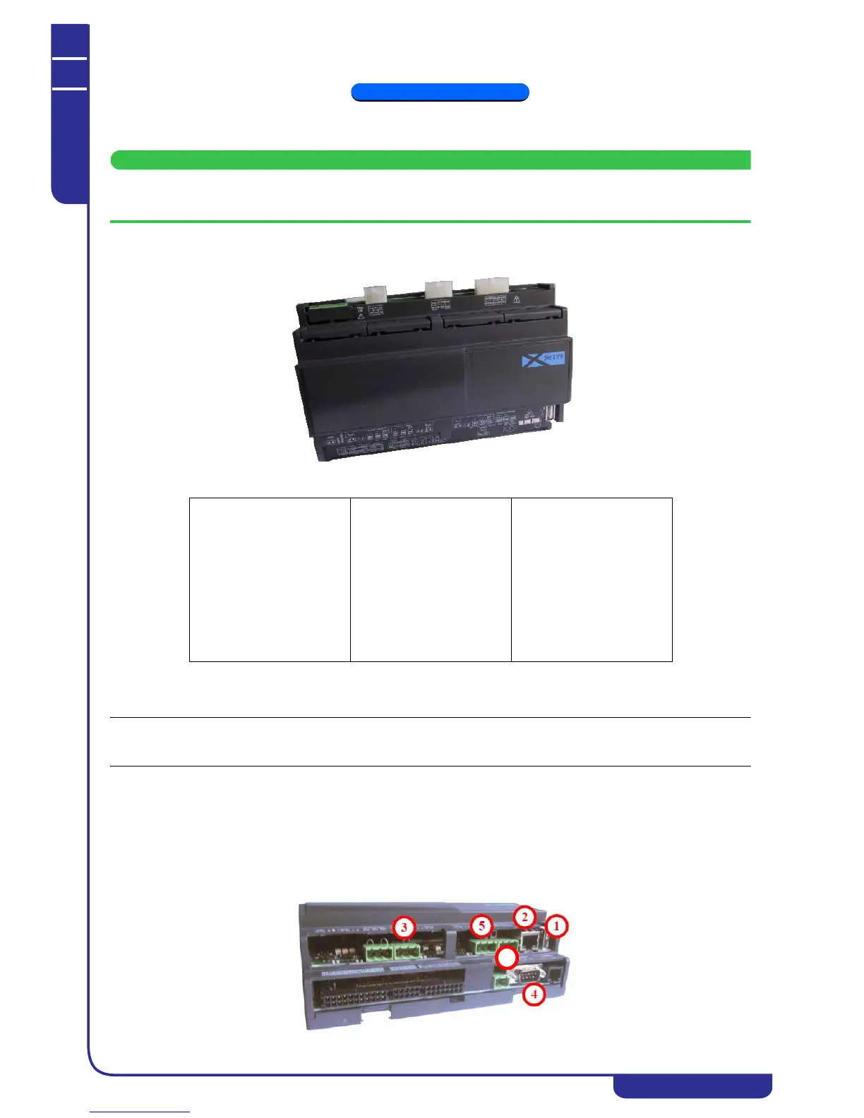
6.1.1 Controller connectivity
The xDRIVE controller communicates with the other hardware devices in the unit (display, drivers, auxiliary modules) by
means of the CanBus port (5) or the display port (6). There are also several additional serial ports:
1. USB: used for installation and subsequent upgrading of the controller software
2. RJ-45 (Ethernet): used to connect the unit to an Ethernet network and for communication in a modular system
3. RS-485 (MODBUS): used for communication with other devices by means of the MODBUS protocol
4. RS-232 (GSM): used to connect an external modem to the controller (optional)
Power supply
12V/24V ac/dc
Digital inputs
20 optically coupled
Analog inputs
10 configurable
Analog outputs
6
Digital outputs
15
Serial outputs
1 USB
1 Ethernet
1 RS232 (optional)
1 RS485 master
1 RS485 slave
1 CAN-BUS output
Operating system
Linux
CPU
200MHz
Processor
32bit
RAM
32MB
Flash memory capacity
128MB