MAINTENANCE AND OPERATING MANUAL
Electronic controller
HAS T 070÷140
80
ENGLISH
EN
The data in this manual are not binding and they can be modified by the manufacturer without notice. Reproduction of this manual is strictly prohibited.
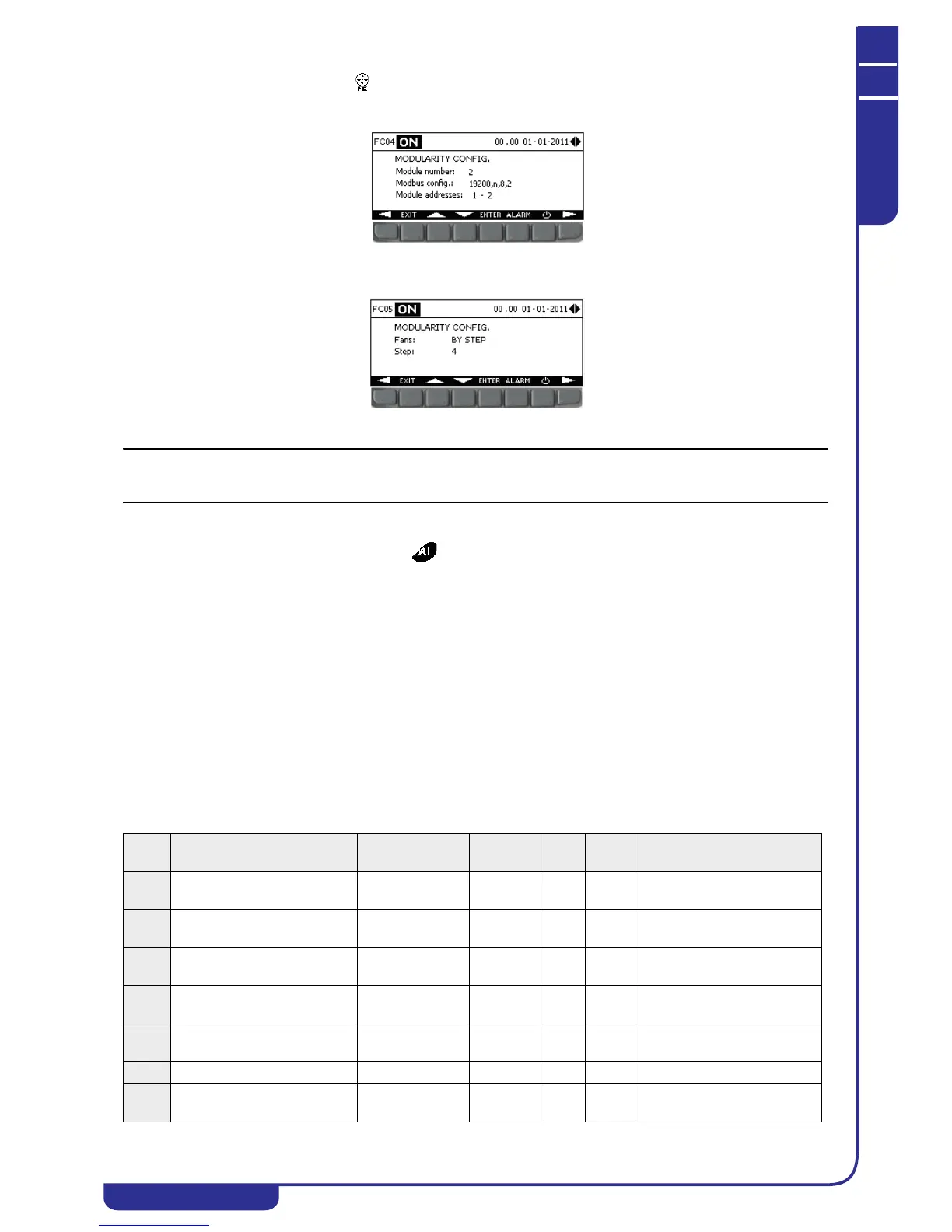
2. Open the free-cooling menu and set up the parameters for communication with free-cooling modules in mask
FC04, specifying the number of modules connected, the Modbus communication utilised, and the Modbus
addresses of the modules;
3. In mask FC05, specify the type of fans installed in the connected free-cooling modules and the number of steps, in
the presence of step-controlled fans;
4. Set up the configuration parameters on the free-cooling modules electronic controller (see specific manual).
Correct communication between the unit and the external free-cooling modules is indicated in mask IF01 in the I/O menu
(see "6.3.1 EX/MD auxiliary I/Os" .
6.7.22 Other settings
The following operations can be performed in the menu:
• change user password
• define an offset on all the unit's temperature and pressure probes
• display enabled probes and their measurement range
6.8 Alarms
An alarm situation is signalled in the unit by means of an audible signal (buzzer) and the appearance of the relative message
in the display ALARM menu. Depending on the alarm type, the system either suspends operation of a circuit, of a single
device, or of the entire unit.
6.8.1 Buzzer
In the case of an alarm, the display activates the buzzer continuously if the alarm concerns the entire unit, or intermittently if
it concerns a single circuit.
The buzzer can be enabled from the display in the USER menu.
6.8.2 Alarms list
The following list shows the possible alarms that may be tripped on the unit:
Alarm
code
Alarm description Controller action Operation Reset
Active
in OFF
Notes
A001 Unit maintenance Warning on
display
Immediate Auto No If operating hours > defined
setting
A002 Pump 1 overload Unit OFF/Pump 2
ON if enabled
Immediate Man. No Digital input
A003 Pump 1 maintenance Warning on
display
Immediate Auto No If operating hours > defined
setting
A004 Pump 2 overload Pump 1 On if
enabled/Unit Off
Immediate Man. No Digital input
A005 Pump 2 maintenance Warning on
display
Immediate Auto No If operating hours > defined
setting
A006 -- -- -- -- -- --
A007 Tank level Unit Off Delayed Man.
/Del.
No Digital input