MAINTENANCE AND OPERATING MANUAL
Functions and components of the unit
HAS T 070÷140
90
ENGLISH
EN
The data in this manual are not binding and they can be modified by the manufacturer without notice. Reproduction of this manual is strictly prohibited.
• pressure transducers, powered directly by the controller;
• temperature transducers.
7.3.1 Pressure transducers
Each refrigerant circuit is equipped with a low pressure transducer and a high pressure transducer.
These sensors detect compressor suction and discharge pressure values and adjust operation of the unit on the basis of the
programmed set-points.
By reading the parameters the following functions can be controlled for each circuit:
• high pressure alarm;
• low pressure alarm;
• unloading for high pressure;
• low pressure pump-down (not enabled);
• fans control;
• measurement of high and low pressure values.
Therefore, if pressure in one circuit increases or decreases with respect to the preset limit values, an alarm signal can be
tripped to stop the unit, start or stop the fans, and stop one or more compressors after a programmable time interval.
7.4 Flow switch
When fitted with plate evaporator, the unit is equipped with a vane-type flow switch to monitor the correct circulation of
water inside the evaporator. If the circulation fails, an alarm system cuts out the unit after the preset delay. When the flow of
water is restored, the unit can be restarted by pressing the ALARM button. This situation should only occur very occasionally
and for short times.
7.5 Level sensor
All units with storage tank are equipped with a level sensor.
The sensor is installed inside the tank to detect any water losses. If water losses are detected, the sensor sends an alarm signal
to the control board, triggering an immediate shutdown of the unit.
Take all possible precautions to avoid accidental contact with live components.
The voltage inside the electrical panel may reach potentially fatal levels.
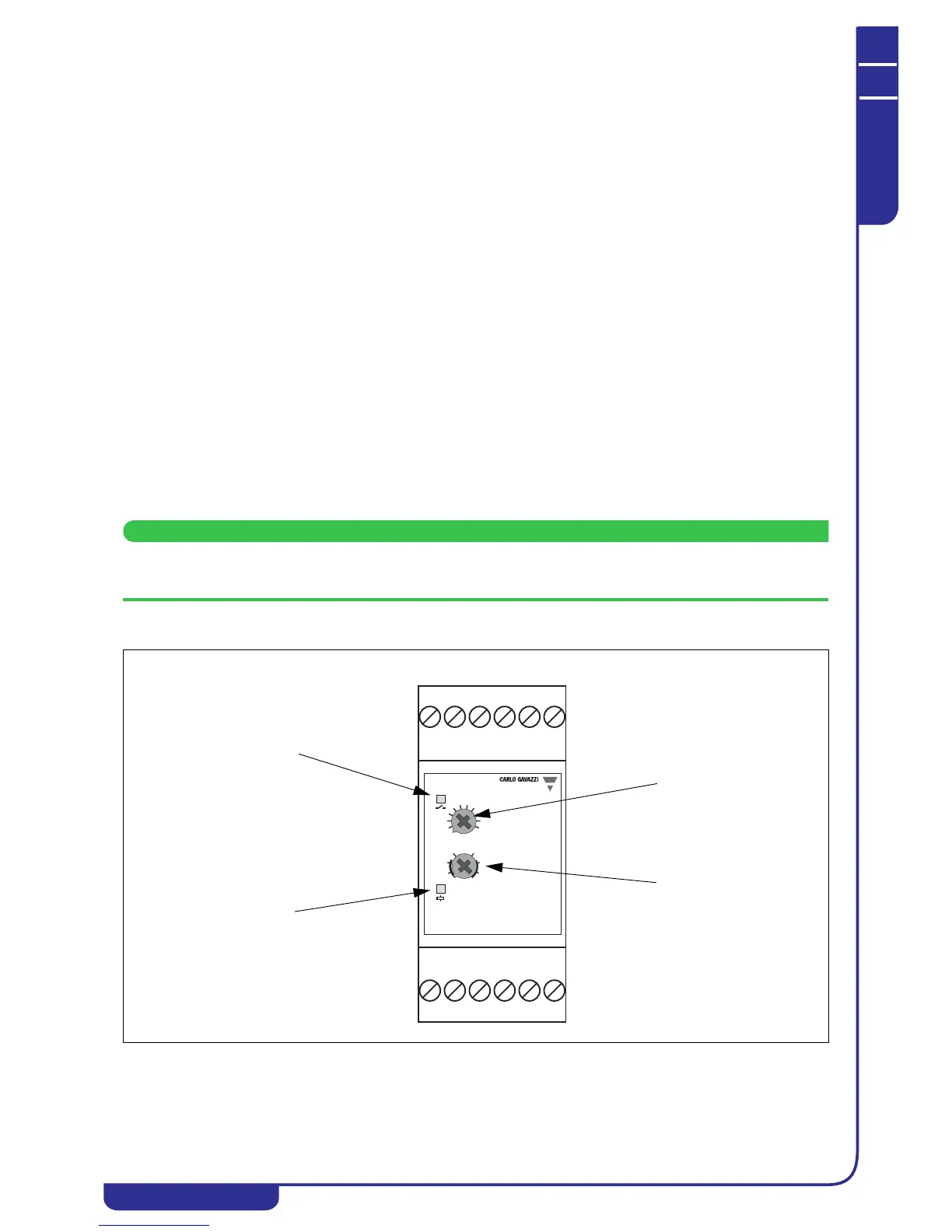
The Orange LED lights up
with water present (during
normal operation) and
goes out in the event of
water losses.
Power up the system; the
green LED will illuminate
steadily.
A Sensitivity setting
B Sensitivity setting
range
Conductive Level Controller
Dual Function
Sensitivity
1
2
3
10
4
56
8
7
9
Fill Empty
L
S
H
L
S
H
11 12 14A1Y2
A2
24
2122Y1Y3