For details of the Modularity function consult the specific manual.
7.1 Electronic thermostatic valve (optional)
The units can be equipped with electronic thermostatic valves.
The electronic thermostatic valve is controlled by the EVD Evolution driver, which processes information it receives from
the pressure and temperature transducers.
EVD Evolution provides rapid and high precision control of superheating, thereby optimising the efficiency of the unit.
The menu is accessible by means of the service level password and with electronic thermostatic valves installed in the unit.
An electronic thermostatic valve adjusts the refrigerant flow rate to the evaporator on the basis of the superheating value
obtained by measuring evaporation pressure and compressor suction temperature. The use of the electronic lamination device
in place of the conventional system makes it possible to operate with significantly lower condensing pressure values (night
time, regions with cold climates, winter season); this device allows the use of extreme capacity control strategies up to 20%
of the total cooling capacity without risking hazardous liquid backflows or evaporator instability, avoiding the harmful
evaporation pressure fluctuations associated with mechanical control.
7.2 High pressure switches (HP)
High pressure switches provide an additional electromechanical protection with respect to the protection offered by the high
pressure transducers installed in the unit.
HP switches are installed on the refrigerant compressor discharge line to prevent the arrival at pressure levels that are
potentially hazardous for proper operation of the unit and for personal safety.
• All refrigerant circuits are equipped with an automatic reset pressure switch on the high pressure side.
Tripping of this pressure switch opens the compressor power supply circuit (see electrical diagram). When
pressure decreases and falls below the reset point, the pressure switch resets automatically and the unit can be
restarted by pressing the electronic controller ALARM button.
• HAST 120÷140
All refrigerant circuits are equipped also with a pressure switch with manual reset on the high pressure side of
each circuit. Tripping of this pressure switch opens the compressor power supply circuit (see electrical
diagram). When pressure decreases and falls below the reset point, the pressure switch must be reset manually,
after which the unit can be restarted by pressing the ALARM button on the electronic controller.
The high pressure switches are connected to the refrigerant circuit pipes by means of SCHRAEDER valves (with needle) so
there is no risk of refrigerant escaping if the pressure switches are to be replaced.
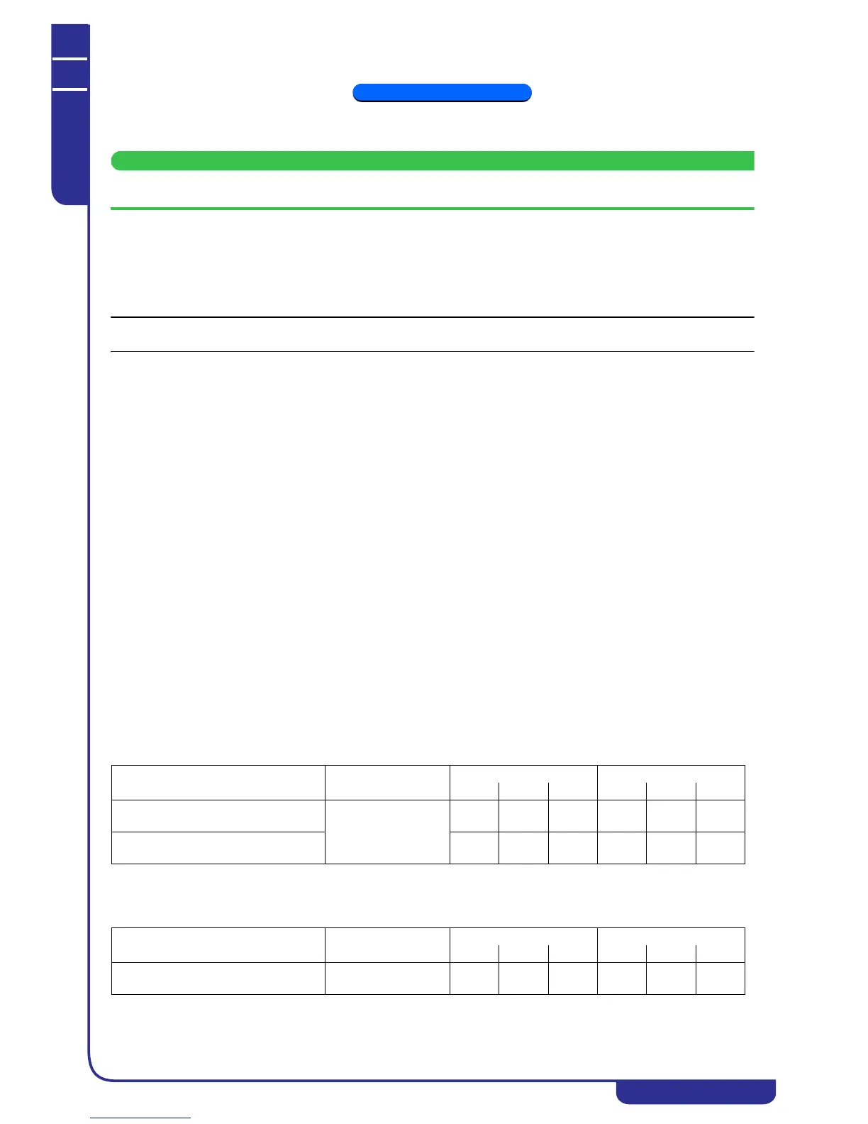
For correct operation of the unit the pressure switch trip and reset values must not differ from those shown in the following
table:
As an alternative to the pressure cartridge type automatic reset HP switch the unit can be supplied with an automatic reset HP
switch of the manual calibration type. The TRIP and RESET values of the pressure switches are given in the following table
and must not be changed:
7.3 Temperature and pressure transducers
The unit is equipped with two types of transducers:
COMPONENT REFRIGERANT
TRIP RESET
bar °C °F bar °C °F
High pressure switch
with manual reset
R410A
40.4 63.4 146.2 36.4 58.8 137.8
High pressure switch with automatic
reset (pressure cartridge type)
39.0 61.9 143.4 30.4 51.0 123.9
COMPONENT REFRIGERANT
TRIP RESET
bar °C °F bar °C °F
High pressure switch with automatic
reset (manual calibration type)
R410A 39.8 62.8 145.0 33.8 55.6 132.1