MAINTENANCE AND OPERATING MANUAL
Installation
HAS T 070÷140
42
ENGLISH
EN
The data in this manual are not binding and they can be modified by the manufacturer without notice. Reproduction of this manual is strictly prohibited.
For correct operation of the unit install a filter to intercept debris in the water inlet pipe. Failure to observe this prescription
can result in irreparable damage to the evaporator.
In the case of plate evaporators, the clogging of even a few plates (or gaps) can cause the plate to seize (clogging), leading
to damage of part of the exchanger, even if water flow seems regular and operation is apparently normal.
The hydraulic circuit must be sized in such a way as to comply with the pressure limit value specified on the data plate and
ensure the flow rate shown in the following table is not exceeded:
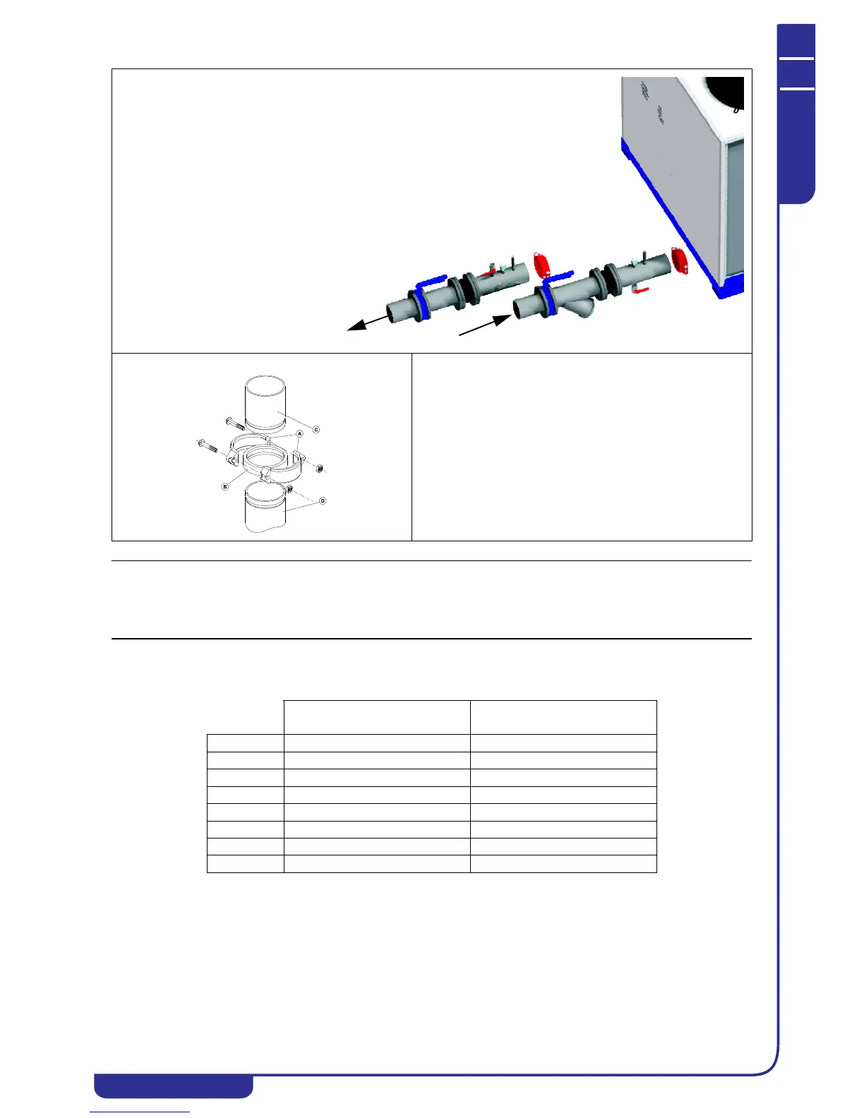
Typical water side connection
1. “Victaulic” connections
2. Thermometer
3. Pressure gauge
4. Air bleed valve
5. Discharge valve
6. Anti-vibration coupling
7. Shut-off valve
8. Filter with removable filter
basket
“VICTAULIC” CONNECTION
A clamping half collars
Bseal
C weld-on stub pipe
D evaporator stub pipe
PLATE EVAPORATOR
Minimum flow rate [m
3
/h]
PLATE EVAPORATOR
Maximum flow rate [m
3
/h]
HAS T 070 13.0 42.1
HAS T 080 16.2 48.2
HAS T 090 18.0 52.2
HAS T 100 19.4 55.8
HAS T 110 23.0 61.9
HAS T 120 24.8 74.9
HAS T 130 27.4 81.7
HAS T 140 30.2 88.2